|
|
GENERAL EQUIPMENT INC.
8724 Sunset Drive #191● Miami FL 33173 · USA
|
|
|
GENERAL EQUIPMENT INC.
8724 Sunset Drive #191● Miami FL 33173 · USA
|
TITAN130
|
TYPE: |
Generator |
|
DESCRIPTION: |
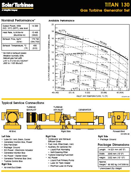
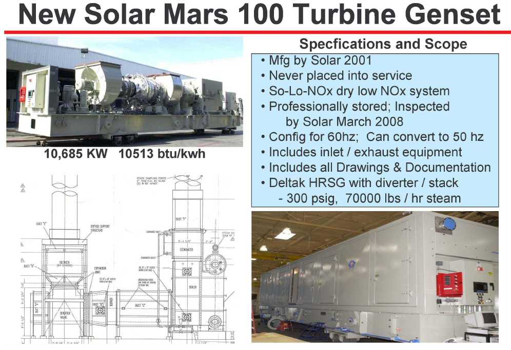
Titan 130 Industrial Power Generator 15 MW |
|
PRICE: |
Upon Request |
|
PACKING: |
Ex-Works |
TITAN 130 INDUSTRIAL POWER GENERATOR 15mw
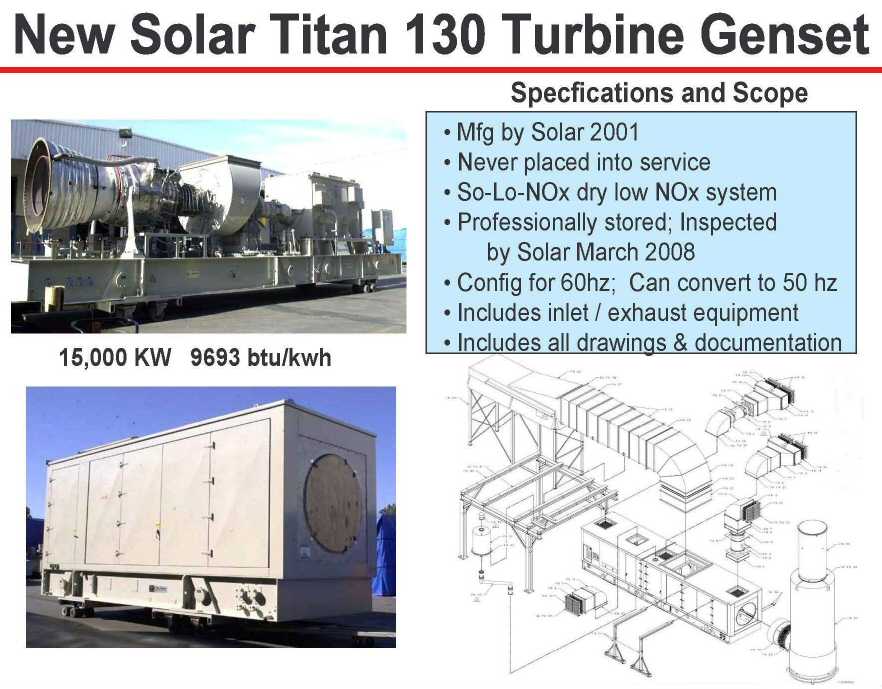
BASIC PACKAGE
The Titan 130 Industrial Power Generator (IPG) is a compact, rugged gas turbine generator set that has been designed to meet the requirements for industrial power generation applications. The unit is provided as a completely integrated module ready for installation. The gas turbine engine, gear box, generator, control system, fuel system, lubrication system, start system, and ancillary equipment are included in the package.
Features included in this proposal are:
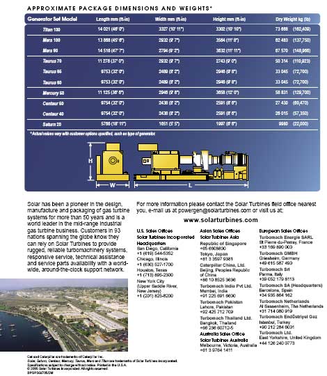
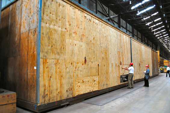
Base. The base provides structural support for the Titan 130 gas turbine engine, gear box, generator, enclosure, and all operating systems. The base is manufactured by Solar using structural steel with welds per AWS D1.1. Approximate overall dimensions are:
48 feet, 0 inches (14,629 mm) long
10 feet, 4 inches (3,150 mm) wide
Approximate height of package is 11 feet, 3-1/2 inches (3,438 mm) and may vary with ancillary equipment and generator selection. Four lifting gussets are provided.
Drip pans are welded beneath the package frame to collect potential liquid spills. The drip pans also provide a tight seal for containment of fire suppression agent for packages supplied with an enclosure.
Piping. All tubing and piping up to 4 inches nominal diameter is stainless steel. Package piping is designed and fabricated to ANSI B31.3.
Tube Fittings. All tube connections use compression fittings. Tube fittings are zinc plated carbon steel or 316 stainless steel.
Note: Throughout the proposal, all references to the package orientation (left, right, clockwise, counterclockwise, etc.) are based on standing at the "aft" (e.g. turbine exhaust) end of the package looking forward.
Electrical System. The Titan 130 IPG generator set is designed to comply with the requirements of the National Electrical Code and is intended to be installed in a non-hazardous location per NFPA 37.
Unless otherwise noted package motors and heaters are rated for 460 Vac, 60 Hertz, 3 phase. Except where indicated, contactors and motor starters are not included.
Unless otherwise noted single phase loads are rated for 120 Vac, 50 - 60 Hertz.
GAS TURBINE ENGINE
The Titan 130 gas turbine engine is a single shaft, axial flow engine. The output gearbox, including accessory drive pads, is a separate, close-coupled unit located at the inlet end of the turbine.
The engine assembly consists of:
· Gear unit with accessory drive pads
· Air inlet collector with flexible flange connection
· Axially split case in the vertical plane, 14 stage axial flow compressor with variable geometry control on inlet guide vanes and first three rows of stators
· Annular combustor with 14 fuel injectors
· Three-stage turbine assembly
· Turbine exhaust collector
The components of the Titan 130 engine are maintained in accurate alignment by mating flanges with pilot surfaces and are bolted together to form a rigid assembly. The speed reducing gear box is driven by the compressor rotor shaft. Accessory pads drive the main lube oil pump and other accessories, depending on the application, and supports the starter motor.
The gas turbine output shaft is mechanically coupled to both the compressor and turbine sections of the engine to form a "solid" or "single" shaft configuration. This feature enhances speed stability and response under constant and varying load conditions -- a highly desirable feature in generator applications requiring precise frequency control.
Inlet Orientation. The gas turbine air inlet flange terminates in the up position.
SPEED REDUCING GEARBOX
The speed reducing gearbox is an epicyclic star-gear industrial design manufactured to Solar's design specifically for the Titan 130 IPG generator set. The gearbox mounts directly on the Titan 130 gas turbine to reduce engine speed to 1800 rpm (60 Hz).
GENERATOR
Generator Rating. The generator is rated per NEMA standards so that the generator will not limit turbine performance over the range of site ambient temperatures.
Generator standard features include:
· Sleeve Bearings with pressure fed sumps
· Six-lead WYE connection
· Terminal box
· Form wound stator windings
· Damper windings
· Rotor balance to 125% rated speed
· Permanent magnet pilot exciter
· Anti-condensation space heaters
· 300% short circuit capability for 10 seconds
· Overload capacity per NEMA:
- 150% rated current for 1 minute
- 110% for 2 hours
Voltage Regulator Characteristics
· Solid state
· Single-phase sensing
· ±10% voltage adjustment range
· 0.5% steady state voltage regulation
· Reactive load sharing to within 5% nameplate rating
· Crosscurrent compensation capability
Wave Form Characteristics.
| · Deviation Factor [maximum]: | 6% |
| · Harmonic Content [maximum]: | 3% |
| · Telephone Interference Factor: | 50 |
| · Balanced Residual: | 75 |
Voltage Drift. The change in voltage will not exceed 1.0% over a 30 minute period when the generator is operating at rated voltage and 0.8 to 1.0 power factor and with a constant load between no load and full rated load.
Generator Construction. An open drip proof generator per NEMA standards is provided.
Generator Voltage. The generator output is 13,800 Volt, 3 phase, 60 Hz. Insulation conforms to NEMA class F with class F (105Co) temperature rise.
START SYSTEM
Two direct drive AC motors are provided to start the Titan 130 engine. A variable frequency drive [VFD] motor controller is included for installation in the motor control center [MCC]. Three phase AC power is required at 380-415Vac, 50 Hz/460-600Vac, 60Hz, 360 kVA. The control system provides all required sequencing to quickly and reliably start the turbine.
VFD Communication Cable. Solar to provide the VFD communication cable & end adapters. Cable length to be 100ft.
FUEL SYSTEM
The fuel system, in conjunction with the electrical control system, includes all necessary components to control the fuel pressure, to schedule fuel flow during start-up, and to modulate fuel flow during operation.
Natural Gas Fuel. A natural gas fuel system is provided with all components necessary to maintain turbine speed to provide a constant generator output frequency and/or load depending on the generator set mode of operation. Solar's Specification ES 9-98 contains specific requirements for fuel and combustion air.
The natural gas fuel system includes:
· Primary fuel shutoff valve
· Pilot-operated secondary fuel shutoff valve
· Electronic actuated fuel control valve
· 10-micron pilot gas filter with change switch
· 14 fuel injector assemblies
· Valve check pressure transmitter
· Gas fuel pressure transmitter
· Gas fuel filter
System Requirements
· Requires a constant supply of gas at a maximum flow demand rate of 3500 scfm (104nm3/min) at 360 to 500 psig (2480 to 3450 kPa gauge) pressure.
· The gas fuel should be free of sulfur, contaminants, entrained water, and liquid hydrocarbons.
· Gas fuel must conform to Solar's Specification ES 9-98.
LUBE OIL SYSTEM
A complete lube oil system suitable for operation with lube oil conforming to Solar's Specification ES 9-224 is included. The lube oil system provides oil to the bearings in the Titan 130 gas turbine engine, gear box and generator. Instrumentation, flow control and on frame piping are included.
Main Lube Oil Pump. An engine driven lube oil pump is provided with suction strainer.
Pre/Post Lube Pump. A 3 hp (2.25 kW) AC motor driven pump is provided to supply lube oil flow prior to start up and after shutdown of the gas turbine.
Post Lube Backup Pump. A 2 hp (1.5 kW) DC motor driven pump is provided to supply post operation lube oil flow in the event of power failure. Power is provided by a 120 Vdc battery system.
DC Start Contactor. Solar to provide the DC start contactor.
Drain Line Sight Glasses. Sight glasses are provided on the drain lines from all gas turbine, generator and gear box bearings. Note that some of the gas turbine bearings have a common drain line.
Lube Oil Tank. A carbon steel lube oil tank is provided integral with the package frame. Lube oil level indicator, fill connection with inlet strainer and drain connection are included.
Lube Oil Tank Heater. A thermostatically controlled 10 kW lube oil tank heater is provided. Electric power requirements are 380-575 Vac, 50/60 Hz, three phase.
Lube Oil Vent Separator. An off skid electrostatic precipitator is provided to remove oil vapor from the lube oil tank vent. Recovered oil drains back to the lube oil tank. Interconnect piping between the frame flanges and the vent separator is not included in Solar's scope. The vent separator is nominally rated for less than 0.2 gallons/day (0.76 L/day) oil loss.
Lube Oil Cooler. An air/oil lube oil cooler is provided. The fan is driven by a 5 hp (3.7 kW) AC motor. The lube oil cooler is designed for off skid installation. Interconnect piping between the frame flanges and the lube oil cooler is not included in Solar's scope.
Hail Screen. Solar to include a hail screen over the cooler.
Lube Oil Cooler VFD. Solar to provide a VFD for control of the lube oil cooler fan motors. Included, are the VFD communication cables & adapters. Cable to be 100ft in length.
Lube Oil Vent Separator. An off skid mechanical coalescer is provided to remove oil vapor from the lube oil tank vent. Recovered oil drains back to the lube oil tank. Interconnect piping between the package flanges and the vent separator as well as support structure is not included in Solar's scope. The vent separator is nominally rated for less than 0.2 gallons/day (0.76 L/day) oil loss.
Lube Oil Type. Lube oil is not included in Solar's scope. The lube oil supplied must be consistent with the requirements of Solar specification ES 9-224. This project will be configured for petroleum base oil, viscosity grade C32.
Lube Oil Filter.
Duplex 3 micron oil filters are provided with manual transfer valve, drain,
fill and vent valves, differential pressure alarm transmitter.
CONTROL SYSTEM
Solar's TurbotronicTM control system is provided. The Turbotronic control system is a highly integrated programmable logic controller [PLC] based control system. The control system is installed on the package frame to minimize interconnect wiring.
The control system includes a microprocessor, remote communications modules, chassis based and flex input/output modules, line synchronization module, power supplies and a hardware backup shutdown system.
The control system provides for control of all phases of package operation to include start and shutdown sequencing, normal operation, and malfunction shutdown.
Vibration Monitoring. Vibration monitoring is provided to include three proximity probes, one per bearing, on the engine. One accelerometer is provided with the gearbox. Two velocity transducers, one per bearing are provided with the generator. Preset warning indications and malfunction shutdown initiation are provided.
Temperature Monitoring. Temperature monitoring is provided to include the engine thrust bearing, lube oil drains, lube oil header and the generator bearings and stator windings. Preset warning indications and malfunction shutdown initiation are provided. Ambient, lube oil tank and enclosure temperatures are also monitored.
Audible Alarm. An audible alarm horn is provided to sound whenever the unit has an alarm or shutdown condition. A horn silence push button is mounted on the face of the control panel.
Local Display. The control system is installed on the package frame in weather proof enclosures. A digital control panel [DCP] with all necessary switches and indicators is provided. In addition to display of "first out" malfunctions, the DCP can display:
· System summary/normal running data
· System status
· Digital display of engine and generator parameters
· Alarms and Shutdowns
Gas Compressor Interface. The unit control panel will recieve a start permissive over the DH+ system from the gas compressor system. The Turbines and Gas Compressors will be daisy chained via DH to the Station Panel.
Station Panel for Each Site. Solar to provide a station panel for each site. These panels will have control and display functions for the gas turbine and gas compressors. The Unit Control panel will be required to recieved a start permissive from the gas compressor units. The gas compressor units use Allen Bradley PLC 504. In addition, the station panel will require dial up capability for remote monitoring and alarm notification along with two dry contacts for High/High High level alarm on the sump tank.
Engineering Units. Temperature data is displayed in oF. Pressure data is displayed in pounds per square inch [psi].
Language. Package labels and screen displays will be in English.
On-Crank/On-Line Cleaning. An On-Crank and On-Line engine cleaning system is provided. The systems are independent of each other and include separate distribution manifolds and injectors in the engine air inlet collector and associated onskid plumbing to deliver water and/or approved cleaning solution to the manifold.
Water and cleaning solutions used for engine cleaning must comply with Solar Specification ES 9-62.
Supervisory Interface. An RS 232C/422 interface module is provided to give the user's supervisory computer access to the Turbotronic control system data. Limited control capability is provided to allow the supervisory computer to start and stop the unit, reset alarms, and raise/lower speed and load set points. The communications protocol is Allen Bradley's DF1. The interface module may be located up to 10,000 feet (3,048 meters) from the turbine control system and located up to 50 feet (15 meters) from the supervisory computer for the RS 232C module or 4,000 feet (1,219 meters) for the RS 422 module. The modules are "table top" units and require 120 Vac, 50/60 Hz power.
DH + Communication. Solar to provide DH+ communication between the gas compressors and station panel.
GENERATOR CONTROL AND MONITORING
Integrated monitoring and control of the generator is provided using a specially designed module in the PLC to receive input data from potential and current transformers. The system calculates real and reactive power, power factor and the variables required for synchronization.
Automatic Synchronizing. An automatic synchronizer is provided with the control system to automatically synchronize the unit to the bus through push-button control on the digital control panel [DCP] or by receipt of an appropriate remote signal. A synch check relay is provided as an additional permissive and for backup protection.
Motorized Voltage Adjust. Raise/lower voltage push button control is provided on the digital control panel to control a motorized potentiometer for voltage control. An additional raise/lower switch, supplied by others, may be used to control voltage from a remote location.
KW Controller. A kW controller is provided to control the real load (kW) on the generator set while operating in parallel with a utility or other large source. The kW controller monitors the load carried by the generator set and adjusts the turbine's fuel flow to maintain a constant load as plant load changes. Protection against excessive kW load while in parallel with a large source is provided by the control system "T5" temperature limiter. The kW control system provides additional operational flexibility by allowing unit kW load level to be set at any desired level within the capacity if the unit. The kilowatt load level select switch and level adjustment is located on the digital control panel.
KVAR/Power Factor Controller. A kVAR/power factor controller is provided to maintain a constant reactive load (kVAR) output or constant power factor (pf) on the generator set while the unit is operating in parallel with a utility or other large source. The controller applies a signal directly to the voltage regulator adjust circuit to maintain a constant reactive load or power factor with changes in the infinite bus voltage level. The system incorporates a set point adjust rheostat to set the desired kVAR or pf, a selector switch to choose kVAR or pf control mode, and a switch to turn the controller on and off.
ACCESSORY EQUIPMENT
Battery System. A 120 Vdc battery system is provided to supply power to the backup lube oil pump and the control system. The system includes a wall mount 20 Ampere charger and 100 Ampere-hour lead calcium valve regulated gas recombination batteries on a free standing rack. The system is designed for indoor installation in a non-hazardous area.
The batteries are shipped "wet" with sulfuric acid electrolyte. The batteries are sealed and may be shipped worldwide.
Portable Engine Cleaning System. A portable engine cleaning cart is provided to supply cleaning fluid to on-skid edge engine cleaning system. The cart includes a stainless steel vessel to mix, hold and pressurize the cleaning solution. Compressed air at 550 kPa to 690 kPa gauge (85 to 100 psig) is required.
MISCELLANEOUS
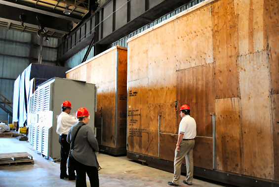
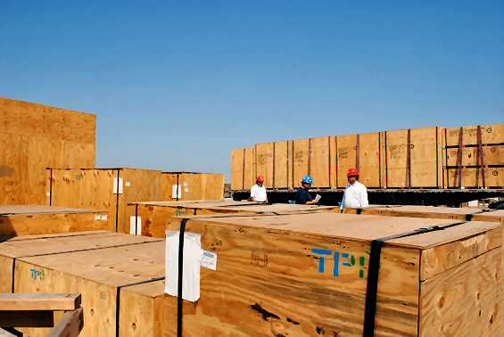
Preparation for Shipment. The package is prepared for shipment with short-term preservation per Solar Specifications ES 9-248-I and ES 9-249.
Shipping Tarp. Solar to provide a shipping tarp for each unit.
Operation and Maintenance Manuals.
An OPERATION AND MAINTENANCE INSTRUCTION MANUAL set is provided. The set includes:
I. System Operator's Guide
II. Installation and Maintenance Instructions
III. Supplementary Data
IV. Illustrated Parts List
V. Quality Assurance Data Book
Four copies of volumes I, II, III and IV are delivered with the turbomachinery. Four copies of volume V are delivered approximately six weeks after the turbomachinery ships.
Operation and Maintenance Manuals - CD ROM. The Operation and Maintenance Instruction Manual (OMI), as described above, is provided on a CD-ROM. One CD-ROM is supplied for each package type per sales order. Additional copies may be ordered at any time for additional cost.
The CD-ROM:
Requires purchaser furnished PC with the following minimum requirements:
· Processor: 486 or better
· Operating System: Windows 3.1, ' 95 or NT, UNIX or Macintosh
· RAM: 16 MB or better
· Available hard disk space: 9 MB or more
· CD-ROM reader drive speed: 2X or faster
· Software: Netscape Navigator Version 4.0 or higher
Includes the following features:
· Electronic viewing of data in a user-friendly windows environment
· All volumes of the manual set on one CD
· Search feature
· Ability to open graphics in a separate window for simultaneous viewing of text with the associated illustration
· Hotspot links include:
· Ability to jump from a referenced table or figure to the table or figure icon
· Ability to view vendor data from links in the Parts List
· Table of content links
Standard Drawings.
Three sets of prints and one reproducible of the following drawings are
furnished per the schedule below:
| DRAWING | INITIAL RELEASE | AS SHIPPED | AS INSTALLED |
| Weeks (1) | Weeks (2) | Weeks (3) | |
| Electrical Schematic | 14 | 4 | 15 |
| Electrical Wiring Diagram | -- | 4 | 15 |
| Electrical Interconnect | 14 | 4 | 15 |
| Logic Block Flow Diagram | 14 | 4 | 15 |
| Software Documentation (4) | -- | 4 | 15 |
| Mechanical Installation (5) | 12 | 4 | 15 |
| Start System Schematic | 14 | 4 | 15 |
| Fuel System Schematic | 14 | 4 | 15 |
| Lube Oil System Schematic | 14 | 4 | 15 |
(1) Standard lead time, Ex-Works, from receipt of order and firm, complete definition.
(2) Standard lead time, Ex-Works, upon readiness to ship unit, or the last unit of a package type on a multiple unit order.
(3) Standard lead time, Ex-Works, upon receipt in San Diego of marked-up field change drawings.
(4) A diskette of the complete software documentation is provided for both the As-Shipped and As-Installed releases. The ladder logic portion of the Software drawing is limited to the As-Installed release only.
(5) Mechanical Installation drawing includes the inlet and exhaust system when applicable.
Alignment Tool. Alignment tooling is provided for aligning the engine power turbine output shaft to the reduction gearbox input shaft.
Mechanical Outline Drawing. A mechanical outline drawing will be provided approximately 6 weeks after receipt of order and firm technical definition. The mechanical outline drawing is a preliminary drawing to be used for foundation design, construction estimates and general information only. The mechanical outline drawing will be issued once. Any changes will be incorporated into the mechanical installation drawing.
TESTING AND QUALITY ASSURANCE
Package acceptance testing is performed at Solar's factory in accordance with Solar's Specifications as generally outlined below. The purchaser or purchaser's designated representative may observe factory production tests scheduled in accordance with production and testing schedules. Unavailability of the purchaser or purchaser's representative shall not be cause for delay in the performance of the production tests.
Inspection and Test Plan. An Inspection and Test Plan (ITP) is provided to describe the Quality Assurance and Quality Control Program requirements for each project. The ITP defines quality requirements for purchased and manufactured material from receiving inspection to the final package inspection. The ITP lists the primary controlling and verifying documents, codes and standards used to define the quality requirements and identifies inspection points. The ITP always includes relevant Solar documentation requirements and can include acceptable Purchaser specified requirements.
Gas Turbine Engine Testing. The gas turbine engine is tested in accordance with Solar specifications to confirm that power, heat rate, and vibration levels meet Solar standards.
Generator Testing. The generator is tested in accordance with IEEE Standard Specifications and Solar's specifications at the manufacturer's plant. These tests satisfy requirements for NEMA and Solar. Supplier testing is under periodic Solar quality control review to ensure compliance with required specifications.
Radiography Inspection. Radiographic inspection is performed in accordance with ASME Section V. Five (5) percent of each welder's work (circumferential butt welds only) is inspected by radiographic examination in accordance with ANSI/ASME B31.3. The specific manifolds on a given unit may or may not be part of the 5% of each welder's work which is examined.
Quality Assurance. All testing operations are conducted under the direct control of Solar's Quality Assurance Activity. This Activity ensures compliance with the specified test limits and procedures.
In addition to final in-plant testing of the finished generator set, Quality Control engineers maintain surveillance over the manufacture of all purchased parts and subassemblies, and are responsible for functional testing of incoming components. The same rigid standards applied to parts manufactured by Solar are applied to all parts from suppliers.
Emissions Testing. The unit will be tested for exhaust emissions of NOx, CO and UHC in accordance with Solar Specification ES9-97.
Field Verification Test. Concurrently with start up and commissioning, as described elsewhere in this proposal, Solar will perform site performance verification per "Site Test Procedure for Solar IPG Generator Sets".
Observe on Noninterference Basis. The purchaser is provided access to Solar's Production Test Facilities to observe factory production tests scheduled in accordance with production and testing schedules. Unavailability of the purchaser or purchaser's representative shall not be cause for delay in the performance of the production tests.
Quality Control Documentation. The following documents are provided:
· Engine and Package Acceptance Test Report
· Solar Certificate of Compliance
AIR INLET SYSTEM
An air inlet system is provided consisting of
the components identified below. The air inlet system is designed to supply
a clean, smooth airflow to the turbine. The air inlet system pressure loss
is as low as is practical consistent with requirements for air
filtration and acoustic attenuation. Pressure loss is normally expected to
be less than 4 inches (102 mm) of water with a clean air filter. All inlet
system components are designed to withstand a 120-mph (193-km/hr) wind load
when properly installed.
Except as noted components supplied with the air inlet system need to be supported independent of the turbine package.
Air Inlet Filter. A weather hood, pre-filter, and barrier inlet air filter suitable for moderate environments is provided. The unit features low velocity weather hoods, pre-filter elements, and high efficiency barrier panel filter elements. The hood assembly is hinged on each side to provide filter access for servicing.
Weather Hood. A weather hood kit is provided for additional protection from rain and snow.
Inlet Screen. A trash/debris screen is provided. Use of the screen avoids clogging and premature filter replacement. During cold weather operations the screen should be removed and stored because of a tendency for it to ice up or clog with snow.
Air Inlet Silencer. An air inlet silencer is provided. The silencer is installed on the enclosure roof without additional support.
Air Inlet Ducting. The following air inlet duct sections are provided. Air inlet ducting, silencer and other air inlet system components need to be supported independent of the package enclosure.
· Transition 45 degree elbow section, engine inlet to 2.3x2.3 m
· 90 Degree Elbow Duct. (1) 90 degree elbow duct to connect back outlet inlet filter with inlet silencer.
Air Inlet Silencer Support. A structure is provided to support the air inlet system.
EXHAUST SYSTEM
An exhaust system is provided consisting of the components identified below. A well designed exhaust system provides the hardware necessary to ensure a smooth transition from the turbine exhaust to the heat recovery system or the exhaust silencer. Ideally, pressure losses should be as low a possible to provide for best possible turbine performance. Typically, pressure losses will be on the order of 4 inches water column (w.c.) (102 mm w.c.) for a system with a silencer and on the order of 6 to 10 inches w.c. (152 to 254 mm w.c.) for a heat recovery system. Exhaust system components supplied by Solar are designed to withstand a 120 mile per hour (193 km/hr) wind load when properly installed.
Depending on the application and responsibilities, some of the components in the exhaust system may not be in Solar's scope. In this event the customer must insure that the components supplied by others are capable of handling high temperature gases on the order of 1,000 oF (540oC). Specific exhaust flow rate and temperature data is included with the performance data in this proposal.
Exhaust silencer and ducting must be supported independent of the enclosure to maintain loads on engine exhaust within limits shown on Mechanical Installation Drawing. Thermal expansion loads can be avoided by proper installation of the silencer and ducting and with the use of flexible bellows connections.
Please note that personnel protection, insulation or lagging is not included in Solar's scope, unless specifically included as part of the heat recovery system.
Exhaust Silencer. A floor standing exhaust silencer is included.
Exhaust Ducting. The following exhaust ducting components are provided. Attaching hardware and gasket are provided for the inlet flange on each component.
· Duct, Exhaust - Turbine to Silencer.
· Bellows, Exhaust - Turbine to Silencer.
· Stack, Rain Protection - Downstream of Silencer.
ENCLOSURE
Basic Construction. An all-steel enclosure is provided for the complete turbine generator package. The enclosure is a self-contained, weatherproof, insulated, and sound-attenuated enclosure assembled on the turbine package skid base.
The enclosure is constructed with a one piece solid roof and non-removable side panels. Enclosure doors are provided in key locations for access to major components requiring inspection and maintenance and for component removal by forklift and overhead crane. The wall area of the engine provides bi-fold doors which open to provide access and clearance for engine and gearbox removal. The enclosure walls and roof are treated with fiberglass material for noise attenuation and thermal insulation. The enclosure is constructed to support a roof load of 50 pounds per square foot and to withstand a wind load of 120 miles per hour.
The unit digital display panel is installed in the wall of the enclosure.
Sound Attenuation. The sound-attenuated enclosure is intended for use with suitable turbine air inlet and exhaust silencing systems in environments where lower noise levels are a requirement. Ventilation openings are equipped with suitable silencers for additional sound attenuation. For additional sound data refer to "Noise Prediction, Guidelines for Industrial Gas Turbines (Solar publication SPNP/898/4M).
Exterior Connections. Connections for oil tank vent line, ventilation fan wiring, fire and gas suppression/detection systems, and turbine air inlet and exhaust are terminated outside of the enclosure.
Ventilation System. Enclosure ventilation is provided by a 7.5 hp (5.6 kW) ac motor fan over the turbine compartment. The large fan size provides the airflow required to ensure that the internal air temperature around the turbine remains within acceptable limits. Suitable openings are provided so that an adequate, free flow of ventilation air is available through the enclosure.
Fire Detection and Suppression System. An automatic, electronically controlled fire detection/fire suppression system is installed in the enclosure.
The primary fire detection system utilizes ultraviolet (UV) detectors. The system includes the automatic optical integrity feature, which provides a continuous check of the optical surfaces, detector sensitivity and electronic circuitry of the detector-controller system. Also included is an automatic fault identification which provides a digital display of system status in numerical code.
The secondary detection system consists of thermal detectors. The thermal detectors are designed with "rate compensation."
The two detection systems act completely independent in detecting a fire.
A fire system supervisory release panel is furnished primarily to supervise the fire system circuitry. An open circuit, ground fault condition, or loss of integrity in the electrical wiring will result in a trouble signal.
The enclosure is equipped with a CO2 fire suppression system consisting of a primary total flooding distribution system and a secondary metered distribution system to extend the design concentration of 30% CO2 for 20 minutes. The system is designed in accordance with the U.S. National Fire Protection Association code 12.
Combustible Gas Monitor. A single-channel combustible gas monitoring system is provided to continuously monitor for combustible gases within the enclosure. The gas sensor is monitored by the fire and gas detection/release system.
The start signal is interlocked with the combustible gas monitoring system to ensure the atmosphere is clear prior to initiating turbine engine start. An alarm or engine shutdown is initiated if the gas monitor fails.
Inlet Ventilation Silencer. The enclosure ventilation openings are equipment with roof mounted elbow type silencers with weather louvers.
Exhaust Ventilation Silencer. The enclosure ventilation openings are equipment with roof mounted elbow type silencers with weather louvers.
Dust Protection System. Enclosure inlet vent is equipped with filter units consisting of disposable, barrier type panel filters to remove dust and sand. The exhaust vent is equipped with back draft dampers to prevent dust ingress when unit is not running.
Enclosure Lights. 110 Vac incandescent lights are provided in the enclosure with an on/off switch located near the enclosure door.
Test Kit. A test kit is provided for the UV fire detector and gas monitor sensor. The fire and gas system test kit consists of:
· Combustible gas calibration equipment
· Fire system (UV) test light
· Carrying case for test equipment
Internal Equipment Handling. A turbine/component handling kit is provided consisting of following:
· internal maintenance trolley rails located between turbine air intake and exhaust collectors.
· external (10 ft. long) trolley beam extensions with support frame.
· external, roof mounted, support beam (shipped separately)
· four-ton movable chain fall hoists and lift attachments (shackles and lift strap)
Generator Terminal Box Orientation. The enclosure is configured with the generator terminal box on the right hand side of the package when viewed from the aft [exhaust] end of the package looking forward.
Specification and photos are not contractual and are subject to verification upon inspection
TAKE NOTICE!
PLEASE BE ADVISED THAT INFORMATION INCLUDED IS CONFIDENTIAL IN NATURE AND IS BASED ON PREXISTING BUSINESS RELATIONSHIP WITH THE LEGAL OWNER OF PROPERTY DESCRIBED HEREIN (IF APPLICABLE). AS SUCH, UPON RECEIPT OF SAID INFORMATION THE RECEIVER AKNOWLEDGES THAT ANY UNAUTHORIZED CONTACT WITH SAID LEGAL OWNER WILL BE CHARACTERIZED AS A BREACH OF CONFIDENTIALITY AND SAID AGREEMENT MAY BE ENFORCED UNDER EXISTING LAW OR IN EQUITY.
This paper was prepared by
General Equipment Corp.
The paper represents an offer of a partner of General Equipment Corp.
All rights are reserved by and for General Equipment Corp..
All
content and ideas of this paper are the property of General Equipment Corp.