|
|
GENERAL EQUIPMENT INC.
8724 Sunset Drive #191● Miami FL 33173 · USA
|
|
|
GENERAL EQUIPMENT INC.
8724 Sunset Drive #191● Miami FL 33173 · USA
|
OPLOT120
|
TYPE: |
MBT |
|
DESCRIPTION: |
Oplot 120mm Main Battle Tank |
|
PRICE: |
Upon Request |
|
PACKING: |
Ex-Works |
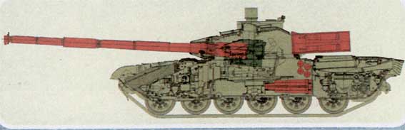
oplot 120mm main battle tank
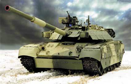
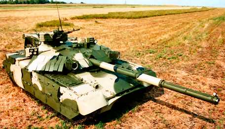
The main battle tank BM «Oplot» is a combat tracked vehicle having the powerful armament, reliable protection and high mobility
The tank is designed to defeat all types of ground (surface) targets by fire
as well as targets low-flying at low speeds under conditions of enemy fire
counteraction
The solution of wide range of combat tasks is possible under different
climatic, meteorological and road conditions in the range of environment
temperatures from minus 40 °С
to plus 55 °С,
relative air humidity up to 98% at temperature plus 25°С.
The altitude range – up to 3000 m above sea level, dustiness of air –
occurring in actual operation
|
Tank components provide as follows:
FIREPOWER: Armament: - main gun - anti-aircraft mount of remote type - coaxial machine-gun Auto loader: - conveyor - automatic loader - control system Fire control system: - sighting system: gunner’s day sight gunner’s night sight commander’s sighting system - main armament stabilizer - armament control system - fire control system: tank ballistic computer input information sensor TBV PROTECTION: Ballistic protection: - armor protection - built-in dynamic protection - anti-mine protection Special aids of protection: - NBC protection system: WMD protection system fire-explosion fighting equipment - anti-detection means: disrupting camouflage painting clamps for natural mantles thermal protection smoke emitter Self- entrenching equipment Elements for installation of mine creeper
MOBILITY: Power pack: - engine - engine systems fuel feed systems air supply system lubrication system cooling system exhaust system warming and heating system starting system Reverse transmission - Complex of automatic control of tank motion - reverse transmission Running gear - track mover - cushioning system deep fording equipment
On the tank, provision is made for installation of the following:
· Vision and orientation devices - day vision devices - driver’s night vision device - orientation device - hydraulic-pneumatic cleaning system of hull and turret devices General electrical equipment elements § Navigation system § General electrical equipment elements |
TECHNICAL CHARACTERISTICS
MAIN PARAMETERS
General data
|
Main parameters
|
Operation data
(for single tank under different road conditions)
|
Obstacles to be surmounted
|
Ammunition allowance
|
ARMAMENT
|
Main gun
120 mm smoothbore gun serves as follows: - to defeat tanks and other armored targets of the enemy; - to suppress and eliminate the fire means and personal of the enemy
To fire the gun, the rounds of separate loading are used – with missile, armour-piercing projectile, heat and high- explosive fragmentation projectiles.
The main type of fire – direct laying, fire. The gun design also allows to deliver fire from closed positions. The gun is loaded by means of the auto loader and in case of its failure, - manually. |
||||||||||||||||||||
|
|
KBA3 gun has
the following design features: visual inspection of liquid quantity in recoil part brakes and recuperator to facilitate the gun maintenance. |
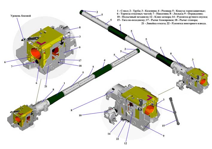
Тank cannon КBА2
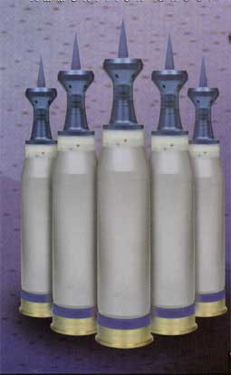
Ammo for 120 mm main gun
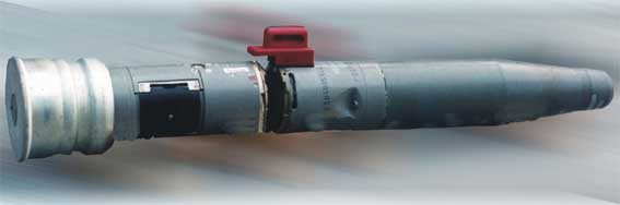
Guided Weapon System
|
When fired from the gun KBА2 of 120mm caliber of the moving or stationary tank, the missile is intended to destroy the following: · objects, having combined, separated or solid armour; · armoured targets such as armoured transporters; · helicopters. Control system is semiautomatic, ensuring teleorientation in the beam of the quantum generator with wave length l = 1.06 µ, tracked by the gunner from the control panel of the sight.
Active and
passive interference resistance is provided.
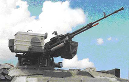
Anti-aircraft
machine gun mount Anti-aircraft machine gun mount (ЗПУ) is designed to protect the tank against air destruction and it is an additional aid for the battle against light armored ground targets.
Anti-aircraft machine gun mount
Machine gun
Autoloader
Autoloader is
a mechanism designed for automatic loading of the gun by any type of a
projectile and consisting of a conveyor, autoloader and control system. It
is hull-located in armoured compartment. Bustle-mounted conveyor
Hull-located loading system
Location of МЗ in tank
МЗ
on turret
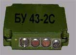
Autoloader control system in the tank is designed for: - controlling the operation of mechanical and hydraulic M3 assemblies; - controlling firing circuits for firing main gun and machine gun; - storing the information on types of rounds loaded in the M3 conveyor.
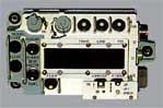
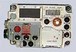
Controls and blocks of Control system integrated gun-and-fire control system (GFCS)
Sighting system 1G46М day gunner sight
Night
Thermal-imaging gunner sight
„Buran-Katrin-E” It is designed for observation, detection, recognition and identification of targets and provision of the gun and the machine-gun aimed fire under all operation conditions. Provides doubling of commander firing.
Commander’s sight system PNK-5 (with sight TKN-5)
It is designed for observation, detection, recognition and identification of targets and provision of the gun and the machine-gun aimed fire in an override mode of fire control by the commander under all operation conditions, designating the target as well as firing the anti-aircraft mount.
Sight ТКN-5
Anti-aircraft mount sight
Gun stabilizer provides stabilization and stabilized guidance of the gun in elevation and azimuth.
Guided missile system
Guided missile system is designed for providing tank gun effective firing through the built-in-gunner-sight laser channel for guiding the missile.
Fire control system
Tank ballistic computer LIO-V
Tank computer input data sensors
Roll sensor
Designed for measuring the position of the gun trunnion axis and inputing the relevant data in the tank computer.
Wind sensor
Designed for measuring the wind speed considering its direction and inputting the relevant data in the tank computer.
Tank speed sensor
Designed for changing the speed of the tank proper and inputting the relevant data in the tank computer.
Turret position sensor
Designed for measuring the angular position of the turret relatively the tank hull (course angle) and inputting the adequate data in the tank computer.
BALLISTIC PROTECTION
Armor protection
Explosive reactive armor (ERA)
ERA kit is designed for improving the tank protection level from HEAT and AP projectiles. The armor protection with ERA provides the protection against: - hand anti-tank grenades, hand-held and heavy grenade launcher and recoilless gun projectiles; - anti-tank missiles ‘TOW-2’, ‘Milan’, ‘Shturm-S’; - HEAT projectiles of 125-mm smoothbore tank guns (3BK-14, 3BK-18); - AP projectiles of 120-mm smoothbore tank guns (CL-3069) and 125-mm (3BM-22, 3BM-26, 3BM-42). ERA consists of front module and side skirts mounted on the tank hull as wells modular sections arranged along the perimeter of front and side sections of the turret and containers mounted on the turret roof. Placed in special recesses ‘Nozh’ protection elements reliably operate under the action of all types of hollow-charge hitting means and AP projectiles. ERA elements on the top frontal hull part, frontal turret sections provide the protection against minimum 3 hits of HEAT and AP projectiles on the part (front module or turret side) and against four hits of anti-tank air bombs - on the turret roof, against two hits of HEAT projectiles or three hits of AP projectiles - on the hull sides. ‘Nozh’ protection elements integrated in ERA do not detonate at the impact of 12.7-mm bullets, AP projectiles of up to 30 mm and projectile fragments, they are safe when handling. When the dynamic protection is hit by the above bullets and projectiles as well the HEAT and HE projectile fragments, this results in explosive ignition without transition to detonation. ‘Nozh’ protection elements are stored in a container or in the tank in heated storehouses or outside under a shed on the ground protected from atmospheric precipitation and sun radiation, at a temperature from minus 50 °С to +55 °С. The relative air humidity is allowed to be 100% at a temperature of +35 °С. ‘Nozh’ protection elements are serviceable within 10 years, including storage under field conditions for minimum 5 years and operation in the tank for minimum 3 years when observing the operation, transportation and storage rules. The tank ERA is brought in combat position within 2.5…2.6 hours without special facilities by the tank crew by arranging the elements of dynamic protection.
Mine protection
The mine protection provides saving the crew’s combat power and serviceability of the tank equipment when blasting the mines under the track with trinitrotoluol equivalent of 10 kg, and under the bottom (in the front compartment) the mines with that of 4 kg.
SPECIAL PROTECTIVE MEANS
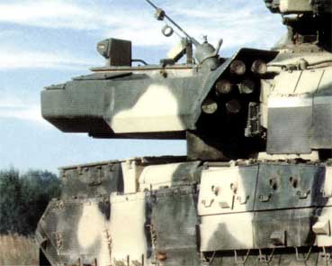
Aerosol screen laying system
Collective protection system
The collective protection system provides protection of the crew and inner equipment from effect of destruction factors of nuclear explosion, radioactive, poison-gases and bacteriological agents as well as detection and suppressing of fire in crew and engine-transmission compartments.
NBC system Radiation and chemical agents detector PRHR-M1 PRHR-М1 (RCAD) is designed for continuous check-up, detection, signalling and control using actuators of protection means : - during intensive gamma- radiation (nuclear blast); - during gamma-radiation on the contaminated terrain followed by measuring the doze of radiation ; - during detection of poisonous vapors in the air as a result of enemy actions.
The instrument provides light and audible signals in case of detection poisonous agents in the air or gamma-radiation on the terrain as well as it generates commands for switching blower on and shifting over the valve of filtering ventilation unit (FVU) in the filtering position. The instrument provides light and audible signals in case of detection powerful gamma radiation as well as commands for engine shutdown, shifting over the valve of FVU in the filtering ventilation mode, switching off the blower if it was on, followed by switching it on in 30 to 50 sec. The instrument provides checking its electrical circuits by generation commands (or without command generation) to actuators.
Filter-ventilator unit (FVU)
The filter-ventilator unit serves to clean external air from poisonous substances, radiactive dust, biological aerosols, to supply cleaned air into the crew compartment and create overpressure in it, as well as to ventilate the crew compartment during firing and fire-fighting equipment comes into action.
Filter-ventilator unit functions in 2 modes: - Ventilation mode. In this case blower delivers the dust-free air to crew compartment passing by the absorber filter. - Filtering and ventilation mode. In this mode the blower delivers the clean air to the crew compartment through the absorber filter.
Fire suppression system
The system with optical sensors and thermal sensors is designed for detection of fire sources in the crew compartment and power pack compartment and quick suppression, generation of commands for ventilation activation and removal thermal decomposition products from the crew compartment.
Fire suppression is exercised by filling the free space of the compartment with extinguishing compound where fire takes place. For this article proposed are the bottles of 2 litre capacity filled with fire-extinguishing compound Chlalon 114B2 or other compound (as agreed) under pressure of 75 kgf/cm2. The bottles are equipped with high-acting heads and pressure alarms. To provide article survivability the FFE system has two bottles for each compartment (crew compartment and power pack compartment).
Concealing
protection means
Smoke screening equipment Smoke screening equipment is intended for laying smoke screen with the diesel fuel.
Self-digging equipment is intended for digging out individual
trenches. It is mounted on the lower nose plate of the tank hull.
INSTALLATION OF MINE CREEPER
The
tank provides installation of track mine creeper (TMC) that allows to pave
the way for tanks across mine fields.
To
do that the tank hull is equipped special weldings. Driver's compartment
provides place for connection to compressor and electrical systems of the
tank for creeper control.
POWER PACK
Engine 6ТD-2 is a multifuel, 6-cylinder, double-stroke liquid cooling diesel.
The engine is adapted for automatic transmission control. Regulator is equipped the rack travel sensor of fuel pumps. Diesel has speed measuring device for recording the crankshaft rotational speed. In electro-mechanical rotational speed governor used is a special mechanism restricting fuel delivery in the range of speeds from 800 to 2000 rpm. Due to that we provide reduction of optical density of exhaust gases at starting and free acceleration modes. In this fuel apparatus used are nozzles with locking needle. The engine consists of crankshaft mechanism, crank cases, cylinders, shifting over mechanism, compressor, gas turbine and hang-up assemblies: starter-generator, water pump, air compressor TK-150, regulator, fuel priming pump, fuel filters, high pressure fuel pumps, oil centrifugal filter, air distributor and other units. Engine cylinder are arranged horizontally. Each cylinder has inlet ports and outlet ports. Inlet ports serve for blowing and filling the cylinders by air, outlet port provide exhaust gas withdrawal. Improved configuration of the inlet ports provides improvement of efficiency due to perfection of gas exchange process and mixture formation. Exhaust gases leaving the cylinders flow through the outlet collector to gas turbine. Each cylinder holds two oppositely moving pistons. When they move to each other as close as possible formed is combustion chamber. Each piston is connected with its own crankshaft by the connecting rod. These pistons making their reciprocal motion open and close inlet and outlet ports and carry out the function of gas distribution mechanism. In these pistons used are the improved needle bearing of the upper head of the connecting rod and making it possible to increase maximum burning pressure, service life and reliability. The compressor of inlet air provides improvement of the diesel parameter due to more efficient compression process attained by improved aerodynamics of flowing part. Gas turbine converts the energy of exhaust gases into mechanical energy for driving the compressor. The engine is mounted in the power pack compartment. Its installation does not require any adjustment. Axles of the engine crankshafts are arranged laterally to longitudinal tank axle. The engine is fastened in three places. Two yokes fasten it in the rear part and pivoting bearing fastens it in the front.
Engine systems
Fuel system
The fuel system comprises the following: fuel tanks, surge tank, fuel distributing valve, external tank switch-off valve, fuel priming pumps, fuel filling filter, fuel pre-filter, fuel fine filter, centrifugal fuel pump, fuel filling pump with a valve, air separating tank, reverse valve, fuel gauges, pipe-lines.
Engine fuel is stored in the fuel tanks with a total capacity of 1,140 litres. The following fuel is used: diesel fuel, jet engine fuel, petrol and mixtures of these type of fuel. The system ensures supply of fuel to the engine from either of the fuel tank groups separately or from both of the fuel tank groups simultaneously. The fuel system also ensures fuel supply to the auxiliary power unit, which is located on the right fender, by means of the pipe-lines going through the vehicle hull side. Fuel can be replenished through the filling necks of the fuel tanks, as well as by using the filling pump.
The air system of the engine is intended to remove dust from the air that comes into the engine. Air purification is performed in three stages with ejection-type removal of dust. The first stage of air purification is performed at a bunker provided with an inertia grid, while the second and third stages, at a two-stage cassette-type air cleaner. The system consists of an air cleaner with a dust removal ejector, air intake bunker with a inertia grid and ejector that removes dust from the inertia grid. The air cleaner is a two-stage device. The first stage ensures a preliminary removal of dust from air with the efficiency of 99.78 %. After going through the second stage of air purification, the air is purified with the efficiency of up to 99.85 %. The cassettes are the second stage of the air cleaner.
Engine lubrication system
Cooling system
Exhaust system
The system provides cooling outer airflow through radiators, using the energy of engine exhaust gases and exhaust gases release. The system includes compensator; gas duct; adapter, weld to the right side of the engine compartment roof, together with by-pass gas duct, receiver with nozzle device and ejector setting. To provide the cooling of the gas duct joint there are water sleeves with circulating coolant.
Heating system
Engine starting system
TRANSMISSION CONTROL SYSTEM
The transmission control system is intended for the following: - disconnection of the transmission from the engine (clutch); - automatic gear shifting in the entire range of gears, including the multiple reverse speed mode and the mechanical (back-up) mode; - steering of the tank in the automated (electro-hydraulic) mode and back-up (mechanical-and-hydraulic) mode, including skid turning and pivoting in the first forward and first reverse gear; - mechanical-and-hydraulic switching-on of the multiple reverse speed mechanism (four higher speed reverse gears); - interlock of the control mechanisms in case of wrong actions of the driver or in case of incomplete switching-on of the multiple reverse speed mechanism; - built-in testing of the control system (equipment and actuating mechanisms); - switching-on of the brakes in the right and left transmission in case of braking the vehicle on the move or for parking. The design of the control system envisages two control modes: main mode (automated) and back-up mode (hydro-mechanical). In the main automated mode, the system performs automated gear shifting in the entire range of gears (7 forward gears and 4 higher speed reverse gears), steering control, as well as built-in testing of the system components. The system's design envisages an electronic interlock of control commands in case of the driver's wrong actions during gear shifting (by using the control buttons) or switching-on of the multiple reverse speed mechanism. In the back-up hydro-mechanical mode, the driver performs manual gear shifting in the entire range of gears and steering control. The system design envisages an electro-mechanical interlock of the gear shifting control devices and multiple reverse speed mechanism switching-on devices.
Reversible transmission
Reversible transmission is intended to increase the tank speed at forward motion and reverse movement. The enhanced gears of reverse movement provide when necessary quick change of position in combat conditions without tank turning. Reversible transmission consists of two gear boxes with coaxially attached reversible final drives.
Planetary, with friction gear engagement. Provide 7 forward gears and 1 reverse gear. Speed at following gears engaged
Reversible final gears consist of two planetary gear sets. Forward and reverse movement is engaged with tooth-type coupling.
Running gear
Running gear consists of track mover and cushion system. Track mover with rear placement of drive sprockets consists of two idler wheels with track tensioning mechanisms, two sprocket wheels, two tracks, twelve road wheels, ten supporting wheels. Cushion system consists of twelve personal torsion suspensions and six hydraulic telescopic shock-absorbers.
DEEP FORDING EQUIPMENT
Deep fording equipment (DFE) provides for negotiating the water obstacle up to 1.8 m deep without special preparation of the tank («Brod» mode) and water obstacles up to 5 m after installation of special removable assemblies of DFE («PH» mode), as well as engaging in combat after negotiating the obstacle without any special works that require the crew to leave the tank. DFE set includes removable and stationary assemblies. Removable assemblies include: air supply pipe, exhaust pipe with wire rope to disengage the lock, nose bilge pump valve, coax MG port sealing, gun muzzle end sealing, rope with caps for sealing the AIU intake valves of PRHR-M1, back-up communication system, input with signal lamp. Air intake pipe is used for supply of air to the engine of the completely tight tank while moving under water. Exhaust pipe is used for exhausting the fumes to atmosphere while moving under water at the depth of 5 m to exclude penetration of water into exhaust channel when the engine is shut off. Nose bilge pump valve prevents the water from penetrating into the tank through the water discharge port with the inoperative pump. Signal lamp is used to mark the place of the tank while moving through the water obstacle in night conditions. The set of removable equipment is supplied to the tank in a separate box bearing the tank number. In view of using the DFE while negotiating the water obstacles at the distance of not more than a day's range, the DFE removable equipment may be stowed on the tank.
VISION DEVICES
LIO-N NAVIGATION SYSTEM
The navigation support system (NSS) ensures the solution
of the following tasks:
1KPI commander's information panel is designed for input by means of key-boards into the system of initial settings, codes, commands, requests, destination and control points coordinates, as well as telecode messages that are generated from the Russian language symbols or Latin alphabet and digital symbols on the display of alphabet-digital and graphic information, received or input from outside through the radio station or from navigation equipment. It is also used to set the status of the tank – the commander of the respective level (up to the battalion commander) or subordinate (linear) of the respective unit.
1KBI-N information unit provides for: - reading of input data and commands from 1KPI panel keyboard and its processing; - exchange of information ans commands with NSS and radio station; - processing of information received from NSS and radio station; - solution of tasks of: o computing the current coordinates and directional angle; o receipt and transmission of commands with coordinates of point of destination; o gathering of information on location of subordinates; o input, storage and operation of route points; o receipt and transmission of telecode messages; o indication of angle of turn to the driver; - controlling the indicator (screen) of 1KPI panel (indication of information and command messages). 1KVI panel is designed for providing the information for the driver about the value and direction of the tank angle of turn to the point of destination. SN-3700 radio-navigation equipment provides for continuous monitoring of the tank coordinates, its route (only on move) and time according to radio signals of navigation space craft of GLONASS and GPS NAVSTAR via open codes at any point of the globe at any point of time and any meteo conditions. Notes: 1. The data on the own tank position, subordinate tanks, points of destination and route points are displayed on the screen of 1KPI in text of graphic format (at the discretion of the commander). 2. UHF radio stations are used in NSS for exchange of commands, navigation and telecode information via digital radio channel.
General ELECTRICAL EQUIPMENT elements
SIGNAL EQUIPMENT
The MBT OPLOT shall be delivered with standard signal equipment subject to be additionally specified by the Customer.
OPTIONS
|
|||||||||||||||||||||||||||||||||||||||||||||||||||||||||||||||||||||||||||||||||||||||||||||||||||||||||||||||||||||||||||||||||||||||||||||||||||||||||||||||||||||||||||||||||||||||||||||||||||||||||||||||||||||||||||||||||||||||||||||||||||||||||||||||||||||||||||||||||||||||||||||||||||||||||||||||||||||||||||||||||||||||||||||||||||||||||||||||||||||||||||||||||||||||||||||||||||||||||||||||||||||||||||||||||||||||||||||||||||||||||||||||||||||||||||||||||||||||||||||||||||||||||||||||||||||||||||||||||||||||||||||||||||||||||||||||||||||||||||||||||||||||||||||||||||||||||||||||||||||||||||||||||||||||||||||||||||||
Specification and photos are not contractual and are subject to verification upon inspection
TAKE NOTICE!
PLEASE BE ADVISED THAT INFORMATION INCLUDED IS CONFIDENTIAL IN NATURE AND IS BASED ON PRE-EXISTING BUSINESS RELATIONSHIP WITH THE LEGAL OWNER OF PROPERTY DESCRIBED HEREIN (IF APPLICABLE). AS SUCH, UPON RECEIPT OF SAID INFORMATION THE RECEIVER ACKNOWLEDGES THAT ANY UNAUTHORIZED CONTACT WITH SAID LEGAL SELLER WILL BE CHARACTERIZED AS A BREACH OF CONFIDENTIALITY AND SAID AGREEMENT MAY BE ENFORCED UNDER EXISTING LAW OR IN EQUITY.
This paper was prepared by
General Equipment Corp.
The paper represents an offer of a partner of General Equipment Corp.
All rights are reserved by and for General Equipment Corp..
All
content and ideas of this paper are the property of General Equipment Corp.
Defense items are subject to final destination approval and granting of an
export license issued by exporting country's authorities