|
|
GENERAL EQUIPMENT INC.
8724 Sunset Drive #191● Miami FL 33173 · USA
|
|
|
GENERAL EQUIPMENT INC.
8724 Sunset Drive #191● Miami FL 33173 · USA
|
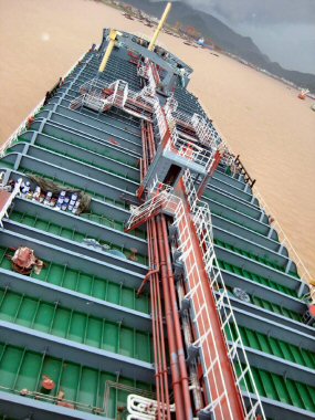
OILTANKER
|
TYPE: |
Tanker |
|
DESCRIPTION: |
Brand New 16800 MT Oil Tanker |
|
PRICE: |
Upon Request |
|
PACKING: |
As is, Where is |
brand new 16800 mt oil tanker

| Dimensions and Particulars | |
| Length over all: | 142.5m |
| Length bet.pp: | 134.5m |
| Breath, mld: | 23.0m |
| Depth, mld: | 12.6m |
| Max draught: | 8.95m |
| Deadweight and Draft | |
| Design draft moulded: | 8.95m |
| Deadweight corresponding here to approx: | 16800 tons |
Speed and Power
4400kw at 520r/min
The service speed on design draft of 8.95m on even keel including 15% service allowance (sea margin) is to be min 13 Knots.
Class Rules and
Regulations
The vessel is to be built according to rules of and under survey of CCS.
GENERAL PART
1.-
General Description: The vessel is a single continuous deck, Double bottom and double hull fitted in way of cargo tanks , a forecastle deck, a poop deck. The ship is a single-screw motor ship with bulbous bow and transom stern2.-
Navigation Zone: The vessel registered as unrestricted service3.-
Mission: The vessel to transport gasoline ,diesel oil, Heavy Fuel Oil(HFO)4.-
Classification: CSA Oil Tanker Double Hull F.P.≤0 , Ice Class B,ESP, CSM BRC5.-
Rules,Regulations and Conventions: The rules and regulations for the construction and classification of sea-going steel ships CCS and subsequent amendments, International Loadline Convention 1966 and subsequent amendments, International Tonnage Admeasurement Convention 1969, International Convention of Prevention of Collisions at Sea 1972 and, subsequent amendments, Marpol 73/78 and subsequent amendments, Solas 1974 and subsequent amendments, International Telecommunication and Radio Regulations and. GMDSS, Rules: OCIMF recommendations and guides on manifold and mooring arrangement, IEC Standards。6.-
Principal Particulars: Length overall about 142.50 m - Length BP 134.50 m - Breadth, moulded 23.00 m - Depth moulded 12.60 m - Draft designed 8.95 m - Deadweight about 16800 t7.-
Tank capacity: Cargo Tank Capacity (incl. slop tanks), 100% full about 19,200m3, slop tanks about 2×100m3, HFO, 100% full (Including day/settling tank) about 800m3, Marine diesel oil , 100% full(Including day/settling tank) about 80m3, Lub. oil Tank, 100% full about 20m3, Fresh water , 100% full about 230m3, Ballast Tank Capacity, 100% full about 7,500m38.-
Speed &Cruising Range: About 13.0 knots at 90% MCR. The ship designed for unrestricted service with a cruising range of 9000 nautical miles at a service speed of 13.0 knots.9.-
Complement: 25P10.- Spare Parts: Spare parts for all equipment are to be provided according to Class requirements and maker’s recommendation
HULL PART
1.-
General: Scantlings shall be in accordance with the requirements of the Classification Society for unrestricted service2.-
Material: The Chemical composition and Mechanical properties of Structural steel material to be quality as required by the Classification Society, Rudder horn to be adopted cast steel, ZG200, 400C3.-
Framing: The hull structure to be adopted combined framing type. For the upper deck and bottom and wing tanks, longitudinal framing type to be adopted, while for other areas transverse framing type to be adopted4.-
Frame space & Camber: Frame space to be 600mm,650mm and 700mm Camber to be 300mm5.-
BRIEF Of HULL5.1
SHELL: The width of keel is 1800mm.Forward strengthened according to the requirement of Ice Class B5.2
BOTTOM CONSTRUCTION: Double bottom arranged in way of the cargo area and engine room the height of Double bottom is 1550mm, for the outer-bottom plating and inner-bottom plating in way of cargo oil region, longitudinal framing type adopted while for engine room ,forepeak tank and aft peak tank, transverse framing type adopted. Pipe casing, the width of which is 1850mm, arranged in way of the Double bottom of cargo area5.3
SIDE STRUCTURE: A double skin arranged in way of the cargo area for the tope, longitudinal framing type adopted while for the bottom, transverse framing adopted5.4
DECKS AND BEAMS: Beams of main deck in way of cargo holds of longitudinal system. All stiffeners and frames arranged outside the cargo tank area5.5
BULKHEADS: One(1) centreline longitudinal continuous oil-tight bulkhead and seven(7) transverse oil-tight bulkhead located in cargo oil tank region. Longitudinal bulkhead corrugated type transverse bulkhead to form of five(5)vertically corrugated type and two(2) flat type corrugated bulkhead without lower stool provided5.6
FORE AND AFTER BODY: The stem fabricated welded steel construction. Perforated swash bulkhead with vertical stiffeners fitted in fore peak tank along the vessel’s centrelines. After body arranged with rudder horn. Rudder horn cast steel5.7
SUPERSTRUCTURES AND DECK HOUSES: For forecastle ,poop and deck house, transverse framing type adopted6.-
OTHERS: Bilge keels fitted on both sides of the vessel for about 30% of the vessel's length, amidship welding to the shell plate on a rider plate and well tapered at both ends. Welding performed for the entire hull structure by manual, or automatic welding according to Builder's practice to Classification Society approval where relevant
DECK MACHINERY, OUTFITTING & INNER DECORATION
1.- DECK MACHINERY: The anchoring and mooring equipment in compliance with the OCIMF Recommendation. Deck machinery provided according to class requirement and to be compliance with the OCIMF Recommendation
No. - Name of Equipment, No. of - set: Type Basic parameter Remark 1 Windlass 2 Electrohydraulic gypsy 15t × 9m / min - hawser drum 7.5t × 15m / min - warping head 3t - 2 hawser drum & 1 warping head - 2 Mooring winch 2 Electrohydraulic hawser drum:7.5t × 15m / min - warping head 3t - 2 hawser drum & 1 warping head - 3 Steering gear 1 Electrohydraulic with 2 pump unit torque ~ 300KN - m - 4 Hose handling crane - 1 Electrohydraulic capacity 10t × 14.5m - Type Basic parameter Remark slewing angle 360°, hoisting speed 12 m / min on full load 20 m / min with light hook - 5 Provision hoist davit - 1 Electric motor driven capacity 1.2t × 7.5m, hoisting speed 10 m / min on full load - 6 Bow thruster 1 Electric motor driven fixed pitch propeller frequency conversion capacity 450 kW
2.- OUTFITTING
2.1 Anchor: Anchor chain Mooring rope Towline and Fireresistant tightwire. Type Basic parameter 1 Anchor 2 Stockless weight 5250 kg - 2 Anchor chain 2 dia. Φ56 mm, total length 577.5 m Grade 3 - 3 Mooring rope - 6 material polypropylene fiber dia. Φ52mm, length 190m - 4 Towline 1 material 6 × 24 tightwire dia. Φ46 mm length 220 m -5 Fireresistant tightwire - 2 material 6 × 37 steel wire rope 1 WRC configuration dia. Φ28 mm length 45 m
2.2. Rudder: The rudder is a streamline, semi-balanced spade type. The area is about 22m2
2.3 Mooring Fittings: Mooring fittings, such as chock, bollards and fairleaders to satisfy relevant OCIMF’S Regulation
2.4 Life Saving Appliances:
Two(2)x 25-man enclosed fire-resistant lifeboat one to be used as the rescue boat. Two(2) inflatable life rafts with capacity 25 persons each or four(2) inflatable life rafts with capacity 16 persons each fitted, one(1) or two(2) at each side. Ten(10) life buoys provided as follows: Two(2) with self-igniting light. Two(2) with self-activating smoke signal and self-igniting light. Two(2) with buoyant lifelines, four(4) life buoys. Life jackets with a light for 31 person shall be supplied; one(1) linethrowing appliance; Two(2) parachute distress rocket signals. Other life saving appliances to include: all together to be five(5) sets of EEBD two(2) in machinery location two(2) in accommodation location one(1)standby2.5 Cargo tank hatch: Each cargo tank has one(1) oil-tight access hatch. The size of cargo oil tank hatch is round with 1000mm dia. The tank hatch has a coaming 760 mm high, main accessory to be stainless steel.
2.6 Smaller Hatches: Hatches of hinged or bolted type provided. The height of hatch coaming shall be in accordance with the requirement of rules Type NO. Size
mm, Location Operation bolted 1 1600× Provision - Location Operation 1600 crane bolted 1 1200×1200 Provision crane hinged 1 700×900 manual - Cargo tank and slop tank cleaning hatch - Tank cleaning hatches of stainless steel construction of suitable size for use with portable tank cleaning machine shall be provided on each cargo tank and slop tank. Number and location of hatches decided in accordance with tank cleaning machine supplier. For an optimal coverage of each tank min.2 hatches arranged for each cargo tank. The dimension of tank cleaning hatch to be about 355 diameter with a height of 300mm coaming.2.7 MANHOLES: Water Ballast Tank, Two(2) manholes of 600
× 800 mm fitted to each tank. Other tanks: Two(2) manholes provided for each tank and one(1) manhole for each smaller compartment. There is commonly arranged manholes 600 × 450 mm. Each tank in fore peak tank, engine room, aft peak tank, steering gear room, closed cofferdams and other closed spaces. There is arranged manholes 600 × 600 mm. Oil-tight manholes provided on each fuel oil tank. Cover bolted with welded on stainless steel studs and stainless nuts2.8 Accommodation ladders: Two(2) sets of accommodation ladder made of aluminum frame and steps provided on upper deck, one for each side of the vessel. The ladder to have the length of about 9.2m to reach the ballast waterline of arrival condition at an angle of about 55 degree to horizontal. It is operated by one man and fitted with winch for compressed air operation. The lower platform fitted with pilot ladder in accordance with SOLAS requirement. The pilot ladders of sufficient length to reach to about 600mm above the ballast waterline of arrival condition.
2.9 Cargo Tank Ladders & Others: Vertical ladders and inclined steel ladders with platform if necessary provided to cargo and slop tank. Vertical ladders of 350mm width fabricated with step of a 24mm square bar. The inclining ladders are as follows: Width 500mm - Step Two 24mm dia. Round bar Handrail & stanchion 25mm dia. round bar Inclining Max. 60 degree from horizon - Other vertical ladder to be of 350 width, and the Other inclining ladders of 600mm width to be of Max. 55 degree from horizon
2.10 Handrail and Storm Rail: The height of handrail 1000mm. Railing builted up with stanchions ,with a top railing of 1.25
″galvanized W.G. pipe , mid railing of 3/4" galvanized W.G. pipes to be arranged between the top railing and the deck. Stanchion 60 × 15 mm steel flat bar,1.5m apart. Storm rails fitted on exposed deckhouse walls and in corridors2.11 Catwalk: Catwalk of steel construction with painted steel open grating provided from accommodation deck to forecastle deck. Handrails, inclining ladders and shield for protection provided on catwalk. The platforms for foam monitors arranged on the catwalk at suitable position in accordance with Rules requirement.
2.12 Mast and Signal: Foremast, radar mast, jack staff and poop staff installed. Signal lamp: signal lamp provided according International Convention of Prevention of Collisions at Sea
2.13 Painting and Cathodes Protections
2.13.1 Painting: All painting works carried. All steel plates greater than 6 mm used for structure shot blasted to Sa 2.5 according to Swedish standard SIS 0559900. Small fittings etc. treated by means of power tools to St 3 according to Swedish standard SIS 0559900. Treated surface to be shop-primer with thickness of 15 microns.
2.13.2 Cathodes Protections: Zinc anodes provided for under water hull parts and appendage ,such as bow thruster, bilge keel, propeller boss and rudder etc.
3.- INNER DECORATION
3.1 Fire protection: The fire protection of the vessel complied with requirement of Solas 1974 and subsequent amendments. The living spaces and services spaces in the vessel are fire protected using IC method.. Exterior boundaries of the poop and deckhouses in the vessel insulated to ‘A-60’ class for the whole of the portions which face cargo oil tanks and 5m aft. Of the front boundary
3.2 Insulation: Accommodation block exposed to weather insulated as follows: Category Materials Remarks Thermal insulation 50 ~ 75 mm thickness rock, wool Exposed surface of accommodation Sound insulation 50 mm thickness partition Between living spaces, office spaces, public spaces and noise generating spaces; Fire insulation: Surface facing to fire
2 × 20 mm ceramic fiber felt Deck 25 mm ceramic fiber felt According to Rules and Regulation3.3 Joiner Bulkhead
Overhead Ceiling: Complex rock wool plate or TC plate fitted.3.4 Deck covering: Materials Room Under layer 8mm thick latex type 1.6mm thick p.v.c. quartz felt - Living spaces, Public spaces 30mm thick cement 5mm thick mosaic tile Sanitary, laundry Floating fire resistance deck covering 2mm thick p.v.c. quartz floor or tile fire resistance spaces
3.5 Doors and Windows
3.5.1 Doors: Weather-tight steel doors located in open position. Doors to be insulated where fire insulation is applied in the wall. Door self-closing devices applied in the A-60 fireproofing doors and the fireproofing doors of stairway. Sound insulation door located in watch-keeping cabin of engine room
3.5.2 Windows: Windows and scuttle for cabins fitted in all cabins accordance with the actual necessary
MACHINERY PART
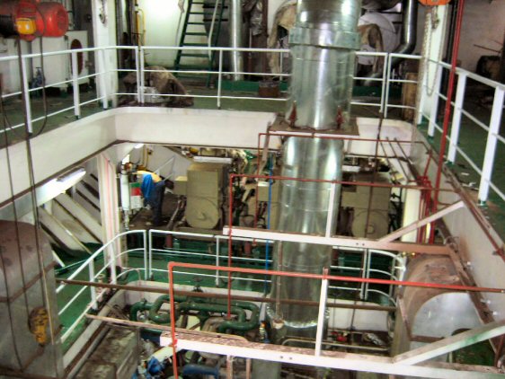
1.- General: The propulsion system is consisting of a medium speed four stroke marine diesel engine driving through a marine reduction gear box, elastic coupling and a fixed pitch propeller. The main engine burns heavy fuel oil with viscosity 1500S under a normal sea going condition and maneuvering, and burn MDO during starting, stop and maneuvering in port
Classification:
CSA Oil Tanker, Double Hull, F.P.≤ 60℃,Ice Class B, ESP
CSM BRC
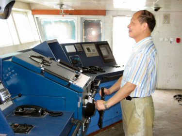
The vessel propulsion plant can be remotely controlled from the bridge control station with the engine room attended by watchkeepers. There’s a engine duty room in engine room, the main engine controlled locally at the engine side or in wheelhouse. The vessel is arranged with three(3) diesel generating sets and an emergency generating set. The main switchboard is arranged in engine duty room, and the emergency switchboard is arranged in emergency generator room
For heating cargo oil, heavy fuel oil, cleaning cargo tanks and general service, the vessel is arranged with a fuel oil boiler (cap. 10t/h) and a composite boiler (when used MDO, steam output about 500kg/h; when used exhaust gas, steam output about 900kg/hr ), the fuel oil boiler shall burn heavy fuel oil with viscosity 1500S the same as the main engine. The compressors and all pumps serve main engine are arranged according to requirements of main engine maker and requirements of rules. For the purpose of determining of the rating of main and auxiliary engines, the following ambient reference conditions apply to the vessel for unrestricted service Ambient temperature 45°, Sea water temperature 32°, Total barometric pressure 100Kpa, Relative humidity 60%, High level alarm of bilge water to be fitted in bow thruster room and pump room
2.- Main engine: The main engine is a vertical type, four-stroke, non-reversible, turbo-charged marine diesel engine. Model 8PC2-6L- M.P.C. Quantity 1- MCR 4400KW - CSR (90%MCR) 3960KW - NO. of cylinder 8 - Cylinder bore 270 mm- Stroke of piston 400mm - Fuel oil HFO with 1500S - F.O. consumption 186g/kwhr + 5% at MCR based on MDO with LHV under ISO reference condition. Rule’s special To comply with MARPOL 73/78 - Annex VI, Regulation 13 (Mandatory code on NOx emission)
3.- Gear box: Quantity: 1 - Model: GWC 70.85 - Reduction ratio: 3.52:1
4.- Shafting: The vessel provided with a single shafting, and the shafting of forged steel to consist of one propeller shaft of solid type. The propeller shaft provided with disconnect coupling flange at fore end. The stern tube shall be of welded construction of seamless steel pipe and welded to the stern frame boss and constructed as a part of hull structure. Stern tube bearings to be oil-lubricated and to be fitted with mechanical seal gears
5.- Generating Sets: The vessel is arranged with three (3) generating sets (each 350kw) and one(1) emergency diesel generating set (90kw, aircooled).
6.- Boilers: A fuel boiler (cap. 10t/hr) is provided to serve for cargo oil heating system and hot water washing system, and a composite boiler provided to serve for HFO heating system and general service
7.- Fuel Oil System: Fuel oil system is designed according to requirements of rules and main engine, auxiliary engines and boilers. Fuel oil system comprise of filling, transfer, purifying, service and drain system. Heavy fuel oil of 1500S used for main engine and boiler. MDO used for the machines at starting. Marine diesel oil used for main generators, and 0# or 10# diesel oil (flash point ≥ 43°) used for emergency generator. Fuel oil systems of auxiliary engines and boiler are independent of each other. The system is arranged with equipments as follows:
1). Two HFO purifiers, automatic self-cleaning total discharge, one can be as diesel oil purifier. The supply pumps for purifiers and heaters (steam heating) are to be supplied with purifiers;
2). One(1) F.O supply unit;
3). One(1) F.O transfer pump: gear pump, 7m3/h x 3kg/cm2 ;
4). One(1) D.O transfer pump gear pump, 7m3/h x 3kg/cm2;
5). One(1) Sludge pump screw pump, 5m3/h x 4kg/cm2;
6). Two HFO setting tanks;
7). Two HFO service tanks;
8). One(1) D.O service tank;
9). One(1) F.O overflow tank;
10). One(1) F.O drain tank;
11). One(1) sludge tank;
12). One(1) waste oil tank.
8.- Lub. oil System: Lub.oil system comprise of filling, transfer, purifying, service and drain system. The system is arranged with equipments as follows:
1). One(1) Lub.oil transfer pump (gear pump);
2). Two(2) main electric-motor Lub.oil pump: flow: 110m3/h, pressure: 0.7Mpa;
3). Two(2) rocker electric Lub.oil pump (flow: 1.2m3/h, pressure: 0.35Mpa);
4). One(1) Lub.oil purifier, automatic self-cleaning total discharge (The feed pump for purifier and
heater are to be loose supplied
by purifier maker);
5). One(1) M/E Lub.oil cooler;
6). One(1) M/E automatic back-flushing Lub.oil filter;
7). One(1) Lub.oil sump tank(the volume to be according to requirement of M/E maker)
8). One(1) Lub.oil storage tank;
9). One(1) Lub.oil standby pump for gearbox; Lub.oil systems of gear box and auxiliary engines are independent of each other
9.- Seawater Cooling System:
Seawater supplied from sea
main by main seawater pump, through Lub.oil cooler, F.W
cooler and gear box , and discharged to overboard. High and low sea chests, at each
side shall be provided in engine room. Two(2) sea chests
arranged in pump room, one for cargo oil pump during storm weather,
and one for two segregated ballast pumps. Each sea chest is fitted
with a seawater filter and a vent pipe. The cooling system of auxiliary
engines is independent
10.- F.W Cooling System: The fresh cooling water is cooled by seawater in F.W cooler (or through the cooler bypass valve but not the cooler), and is pumped to the main engine by electric F.W pump for cooling M/E. When starting the main engine at low temperature or low load, F.W can be pumped to the heater from F.W system or expansion water tank by heating circulation pump. Then for pre-heating the M/E. the auxiliary engine cooling system is independent. The system is arranged with equipments as follows:
One(1) Electric-F.W pump: 140m3/h X 0.35Mpa
One(1) Electric heating circulation pump (also can not to be arranged)
One(1) thermostat valve
One(1) F.W expansion tank;
One(1) F.W heater.
11.- Cooling Water System for
Injectors:
F.W be supplied from F .W
expansion tank (which is located at a height not less than 2m above
the top of cylinder cover) by the dedicated electric cooling F.W
pump, via the F.W cooler (or bypass), M/E fuel nozzles, at last back
to the F.W expansion tank. The system is arranged
with equipments as follows:
One(1) F.W expansion tank (c/w heating device)
Two(2) electric C.F.W pump (discharge capacity:
≥1.0 m3/h ,pressure: 0.35Mpa),one is to be standbyOne(1) cooler
A thermostat valve
12.- The Independent Rocker Lub.oil
System:
The vessel is provided
with the independent rocker Lub.oil system ,and the system
compromise of two Lub.oil pumps, one is to be standby, each pump with
480L/hr
13.- Compressed Air System: The system is provided with two air compressors and two main air reservoirs (30 bar). The two main reservoirs are fully charged within an hour by the two compressors, and to used for starting main engine, A control reservoir (7 bar) is provided for controlling the air(used for main engine) pressure, the capacity of the main reservoir is according to the requirement of M/E maker. The control reservoir (7 bar) charged by the main air reservoirs (30 bar) via a pressure reducing valve. One (1) general service reservoir (300L) arranged for general service, one(1) air horn reservoir (100L) arranged for whistle. A starting air reservoir (400L) arranged for starting diesel generators
14.- Engine Repairing Equipments:
The vessel is arranged
with repair equipments as follows:
1). Engine lathe: center distance: 1500mm
2). Driller: maximum diameter: 30mm
3). Grinder: diameter: 255mm
4). AC electric welding machine: 250 amp
5). Two(2) test tables for F.O nozzles: one for M/E, one for G/E
6). One(1) table vice
15.- Other Equipments In Engine Room
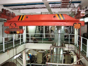
1). One(1) single-rail trolley of main engine
:SWL 5t2). Two(2) axial ventilators in engine room, one is reversible, one is for supplying wind
3). One(1) exhaust fan for purifier room
4). Spark arrestors & silencers of A/E
5). Spark arrestors of composite boiler and oil-fired boiler
16. Engine Room Automatic System
The grade of automatic (“BRC” ) according to requirement of ship owner, that to say bridge remote control, the main engine to be remotely controlled in wheelhouse, also to be controlled locally at the engine side when malfunction of remote control system be happened. The engine duty room is arranged in engine room. Propeller shaft speed and direction indicator, clutch position (ahead, astern) indicator, alarms of gear box( Lub.oil low pressure), alarms of automatic shut down of the main engine when overspeed, the override control switch(for Lub.oil low pressure) and emergency stopping switch are fitted in wheelhouse according to the rules. The engine order telegraph system (contacting to console at the engine side) provided in wheelhouse and at the engine side for controlling M/E. The projects including follows: M/E monitoring and alarm equipment in engine duty room; Remote control gear at bridge
17.- Engine Duty Room In Engine Room:
The engine duty room completed
with a glass window facing M/E and auxiliary engines shall be
arranged with equipments as follows:
One(1) main switchboard and one(1) assembly starting panel; M/E monitoring and alarm equipment (including measure, indicating, and alarm relate to main propulsion) (see the description of
ELECTRICAL PART)
18.- M/E Bridge Remote Control:
The main engine is
controlled in wheelhouse by remote electric-air control system. The M/E manoeuvred at
bridge control console or locally at the engine side.
Control function including
follows: Control locally at the engine
side.
In an emergency, the operation
of starting and stopping the M/E and setting speed can be
controlled locally at the engine side. The button of starting, F.O control
lever and speed setting handle are located at the engine
side.
Wheelhouse control: Remote control the M/E in
wheelhouse, the operation of starting and stopping the M/E and setting
speed can be remotely controlled, the speed controller and speed
setting handle are fitted in wheelhouse
19.-
1. Ballast System:
Ballasting and de-ballasting of segregated ballast water tanks and forepeak ballast tank are carried out by two segregated ballast pumps in pump room. The valves are controlled by electric-hydraulic remote control system, and indicated incargo control room. Ballasting and de-ballasting of stern shaft cooling water tank carried out by G.S pump in engine room. The system is provided with two horizontal centrifugal pumps, which are installed in cargo pump room, the driving motors are placed in engine room. The shaft bulkhead is fitted with a gas-tight stuffing box. Both pumps can be remotely controlled in cargo control room. The remote gauging system of segregated ballast water tanks can be controlled and displayed in the cargo control room. All the ballast valves are of butterfly type, ballast pipes galvanised steel, the thickness of pipes is “C” grade (equal to sch80)2. Bilge Water System: Bilge water in steering gear room is drained to bilge well in engine room through the self-closing valve on inner bulkhead of engine room. Chain lockers, stores rooms in forecastle and cofferdam served by bilge ejectors of 5 m3/h. Drive water supplied by fire/deck
16800DWT wash line in accordance with Rule’s requirement. Emergency suction and bilge pipe system arranged according to CCS rules. An oily water bilge pump and an oily water separator (cap 3m3/h) arranged in engine room3. Deck Scupper System: Sufficient number of scuppers of suitable dimension to fitted to all decks, deck house and casing tops, etc. Plugs furnished for the opening of deck scuppers
4. Gauging System: The level remote gauging system of ballast water tanks is of floating type closed gauging system, which is arranged for cargo oil tanks and slop tanks. The other oil tanks and water tanks are arranged suitable type level indicators according to requirement of rule. Short sounding pipes completed with self-closing valve and selfclosing test cock are fitted for double bottom oil tanks.
5. Firefighting System:
The system provided
according to requirements of CCS and SOLAS as follows:
Cargo tank deck area - Fixed low expansion deck foam
system - Sea water, water hydrants - Engine room, Purifier room - Fixed high pressure CO2 system
- Sea water system, water
hydrants - Portable fire extinguishers - Local mist water spray system - Pump room Fixed high pressure
CO2 system - Portable fire extinguishers - Accommodation Sea water system,
water hydrants - Portable fire extinguisher - Paint store - Water sprinkler system
- Fixed gas detector provided for cargo pump
room - Fire detection system To be fitted in Engine room - Accommodation alleyways, Cabins,
Public spaces and paint store, etc.
5.1 fire main system: The system consists of a fire & G.S pump, a bilge & G .S pump and an emergency fire pump. Fire main served by fire & G .S pump and bilge & G .S pump, and connected to emergency fire pump. Water for washing deck, anchor and anchor chain supplied by fire & G.S pump. Fire hydrants on weather deck and in engine room are 65mm, fire hydrants in accommodation area is 50mm. International shore connections provided. Work water for deck foam extinguishing system supplied by fire & G.S pump
5.2 CO2 fire extinguishing system:
The engine room, purifier room, and cargo pump room are arranged CO2 fire extinguishing system, the capacity of the system according to requirement of rules. The system consists of CO2 bottles, release valve with sign, nozzles, necessary accessories and weighting device. The releasing alarm is electric horn with flash lamp in engine room. Alarm in pump room is whistle; Pump room provided with four(4) portable foam extinguishers (9L), two foam fir extinguishers (135L), two (2) foam fire extinguishers (45L) and ten (10) portable CO2 extinguishers (5.5L)5.3 Foam fire extinguishing system: Calculations for the system complies with requirements of SOLAS and CCS, four monitors and four applicators are provided on the vessel. The system provided with foam proportiner, foam solution tank, monitors, applicators and necessary accessories. The foam water supplied by fire pump and G.S pump in engine room. The main line fitted with several applicator hose connections
6 Steam And Condensate System: The vessel is provided with cargo oil heating system, condensate system, steam system for general service and steam system for heating other tanks
6.1 Cargo oil heating system: The heating and condensate manifold fitted on main deck within cargo area. Condensate is returned to the observation tank (the upper drain pipe of the tank connected with dirty oil tank), and back to the cascade tank; Sufficient quantity of steam traps fitted on the condensate pipes. Material of heating and condensate manifold on deck are “C” grade seamless steel with fire insulation. Heating coil in cargo oil tanks and slop tanks are seamless steel pipe. Heating coil located at a height about 100mm above tanktop, and more heating coil arranged around cargo oil suctions The heating area ratio of cargo oil tanks and slop tanks is 0.04m2/m3
6.2 heating system for tanks:
F.O tanks ,HFO tanks are
arranged fixed heating pipes, heating and condensate pipes for
each oil tank are independence; Condensate form all oil tanks is
returned to the observation tank (the upper drain pipe of the
tank led to dirty oil tank), and back to the cascade tank. Materiel of heating pipes and
heating ratio as follows:
Sample of oil materiel heating
ratio (m2/m3)
HFO seamless 0.099
Black diesel oil seamless 0.02
Remark: more heating coil pipes
to be arranged around F.O suctions
6.3 Steam for general service.: Steam serviced for dry room, steam radiator and airconditioner, and the steam supplied with branch pipes( 0.3Mpa) of system, the condensate water be led to the cascade tank through steam traps
7. Air Compressing System: The compressed air for deck using is supplied by air reservoirs in engine room. Several air hose connections are fitted on air pipes which located on poop deck, accommodation deck and in steering room, air-conditioner room, cargo pump room
7.1 Whistle: Fore mast and radar mast fitted with whistle and fog horn
8. Cargo Oil Transfer Piping System: The vessel can be used for carrying product oil which flash point be less than 60°, MGO, MDO, and HFO (180cst) carried as required. The vessel is to be used for carrying MGO and MDO simultaneously or single kind HFO. The max ratio of loading of the vessel is 1000 m3/hr. When the vessel is to be used for carrying one kind of product oil, only one cargo oil pump to be used, the others are standby. when the vessel carrying two kinds of oil, the two kinds of cargo oil shall be transferred by dedicated pump and piping system Material of gate valves nearby suctions in the cargo oil tank(c/w reach rod operated manually from main deck and c/w open/close indicator) is seamless steel. The cargo loading/unloading station is to be located at midship (P& S), several shore reducer connections (c/w blind flange) arranged according to requirement of rules, inside and outside of reducers to be epoxy painted. The deck zone under manifold shore connections(p&s) of loading/unloading stations provided with spill tank according to requirement, the oil drain pipe of spill tank connected to a cargo oil tank .some cargo oil tanks can be filled ballast water when in bad weather, and ballast water be transferred by cargo oil pump. A fire-proof butterfly valve fitted on the place where the cargo oil manifold penetrating the bulkhead in cargo pump room; The vessel is arranged with drop pipes to each cargo oil tanks used for oil filling, materials of the system contact with oil can not be copper & copper alloy. Consideration of the size of electric station and sample of cargo oil , three cargo oil pumps are provided. the capacity of each pump is 700m3/hr, pressure is 0.8Mpa , the design condition viscosity of fluid is 75cst, power is 315kw .
9. Tank Stripping System: The vessel is arranged with two stripping pumps, the pumps can be used for cleaning or other necessary purposes. Different kind cargo oil tanks are provided with independent stripping piping, Small diameter discharging lines(c/w control valve) of stripping pumps connected to the cargo manifold( between the cargo oil control valve and the shore connection) in the loading/unloading station(p&s) on main deck separately. The stripping pumps are horizontal elec. driven screw pumps (capacity: 60m3/hr, pressure: 0.8mpa)
10. Closed Sounding System: All cargo and slop tanks equipped with remote level measuring system of floating type level gauge with remote readout in cargo control room, a safety level indicator fitted at the loading/unloading station as requirement. A deck valve (gas-tight type) fitted on the deck of each tank for the use of manual sounding, measuring temperature, and measuring the ullage of oil tank. The high-level alarm and overflow alarm of each oil tank (visual and audible alarms) also fitted in cargo control room, another alarm position located on compass deck, so the high- level alarm (visual and audible )can be heard and seen by operators at cargo area. Each level switch is explode-proof. The temperature sensor assembled in floating type sounding equipment, the temperature of oil tanks be indicated in cargo control room. Measure of temperature, high-level alarm, overflow alarm and sounding system are assembled a unit, high-level alarm and overflow alarm are independent of each other, and all are independent of the sounding system.
11. Cargo Oil Tank Washing System: Washing water be pumped out from seawater manifold by washing pump, via the seawater heater ( steam heating to 80
° ) ,then to be pumped to each water supply connection of washing machine on deck . All cargo oil tanks and slop tanks are arranged with portable washing machines except for the NO .1 cargo oil tanks (P & S ) fixed washing machine for the case of two slop tanks located above the top of NO .1 cargo oil tanks. Each tank arranged with one(1) openings for washing tanks, the quantity of fixed washing machines for NO.1 cargo oil tank (P & S) is each one, the discharged capacity of washing machine is not more than 30m3/hr, pressure of work water is 8kg/cm2. Two portable dual nozzles washing machines (c/w rubber hose and supports) are arranged according to requirement of ship owner. The capacity of hot water in heater is enough for washing two cargo oil tanks by two portable (or fixed) washing machines simultaneously. Another washing pump be used for transferring washing water from cargo oil tank to slop tank, washing pump also can be used for transferring bilge water from cargo pump room to slop tank.12. Vent System: Each cargo oil tank and slop tank is provided with one high velocity pressure/vacuum valve, each vertical pipe of the valve are independent of each other. The valve outlets located at a height not less than 2m above the catwalk deck, and the valve outlets of slop tank located at a height not less than 2m above the top of slop tank. The pressure/vacuum valves are set a positive pressure of 0.14kg/cm2 and at a negative pressure of 0.035kg/cm2. Outlets of vent and pressure /vacuum are arranged asvertically upwards as possible (along catwalk). As the requirement of SOLAS, alternatively, pressure sensors fitted in each tank, with a monitoring and alarm device arranged in cargo control room or the position from which cargo operations, such monitoring alarm equipment is also to provide an alarm facility which is activated by detection of overpressure or underpressure conditions within a tank. The monitoring alarm device be used as the replacement of auxiliary vent gear according to requirement of rule.
13. Cargo Tank Gas-freeing: The cargo oil tank is arranged with two portable water-turbo gas-freeing fans with flexible air duct & hose of working water. The fans are located above the opening of washing machine or other opening of tanks when be used, and the work water supplied from fire main Discharge outlet (c/w gas-freeing cover and fire-resistant net) of Each cargo oil tank located as far as practicable from air inlet and a source of ignition, exit velocity of the gas outlet at least 20m/s, and the gas outlet shall be extend not less than 2m above deck level (or top of the tank ).
14. Oil Discharge Monitoring & controlling System: The vessel is provided with oil discharge monitoring & controlling system according to requirement of MARPOL. The system is arranged with equipments as follows: sampling pump, sample treatment plant, dilution plant, sample detection device, counter control device and flow detection gear etc. The oily water of slop tank to be discharged according to the requirement of MARPOL, and following parameters shall be indicated and recorded on counter: discharge capacity /per sea mile, total discharge oil capacity, oily concentration, oily water discharge capacity and so on, The overboard discharge of oily water from slop tanks to be automatically stopped and dumped back to port slop tank upon high oil content. At the same time, the system gives the alarm. The monitoring & controlling system is suitable for white and black oil. Otherwise, according to the requirement of MARPOL, the vessel is equipped with a portable oil-water interface detector for detecting oil-water interface in the slop tanks or for sounding the oil tanks.
15.
Material Of Hull Piping System: Material of valves, pipes and thickness of pipes as following: System Material Wall thickness, Valve material, Remark: Pipes in cargo tanks and pump room Seamless steel “B” grade Cast steel Cargo oil pipe on main deck, Seamless steel “C” grade Cast steel Vent pipes for cargo oil tanks Seamless steel “B” grade Cast iron Washing pipes (on main deck), Epoxy painted seamless steel “B” grade Cast steel Ballast pipes in segregated ballast water tank, Epoxy painted seamless steel “B” grade Cast steel, Other ballast pipes Epoxy painted seamless steel “B” grade Cast iron Bilge pipes Epoxy painted seamless steel “A” grade Cast iron F.O pipes Seamless steel “A” grade Cast steel Lob.oil pipes Seamless steel “A” grade Cast steel Pipes of fire-fighting system Epoxy painted seamless steel “B” grade Cast iron, Foam fire-fighting pipes Epoxy painted seamless steel “B” grade Cast iron, Scupper pipes of weather deck (general) (overboard) Epoxy painted seamless steel Epoxy painted seamless steel “A” grade “D” grade Cast iron Cast steel System Material Thickness Material of valve. Remarks: Scupper pipes of cabins, soil drain pipes (general) (overboard) Epoxy painted seamless steel “A” grade “B” grade Cast iron Cast steel Air pipes on main deck Galvanised steel “C” grade Air pipes in other place Galvanised steel “B” grade Sounding pipes (water tank) (oil tank) Galvanised steel Seamless steel “B” grade “B” grade Filling pipes (oil) Seamless steel “B” grade Filling pipes (water) Galvanised steel “B” grade Heating pipes for F.O tanks Seamless steel “C” grade Cast steel Heating coil for cargo oil tanks and slop tanks Seamless steel Cast steel Steam and condensate pipes on deck Seamless steel “B” grade Cast steel System Material of pipe Wall thickness Material of valve. Remarks: Steam pipes for general service Seamless steel “A” grade Cast iron Air compressed pipes Seamless steel “B” grade Cast steel F.W pipes Galvanised steel and red copper “A” grade Cast iron DN≥40mm Drinking water pipes Red copper Bronze Hot water pipes Galvanised steel and red copper “A” grade Bronze DN≥40mm Seawater pipes Galvanised steel “B&C” grade Cast iron Table 15-2 Insulation Of Pipe insulation Of Pipe SYSTEM Nominal diameter(mm) Thickness (mm) Material Hot & F.W pipes ≥25 20 Molded mineral cotton pipe Steam and condensate pipe (in tanks and Rooms) ≤25 ≤50 20 25 Molded mineral cotton pipe Molded mineral cotton pipe Heating pipes for oil tanks (on deck) ≤50 ≤100 30 35 Molded mineral cotton pipe Molded mineral cotton pipe Table 15-3 Copper Pipe Outside diameter of Wall thickness (mm) pipes (mm) standard Reinforced thickness: 8 1 1.5 - 14 1.5 2 - 22 1.5 2 - 24 1.5 2 - 28 2 2.5 - 40 2 2.5 Table 15-4 Steel Pipe Nominal Wall thickness (mm) diameter (mm) Outside diameter of pipes (mm) A TYPE - B TYPE - C TYPE - D TYPE - E TYPE: 10 17 2.0 2.0 2.5 2.5 3 - 15 22 2.5 2.5 3.0 3.0 3.5 - 20 27 2.5 2.5 3.0 3.5 4 - 25 34 3 3 3.5 4 4.5 - 32 42 3.5 4 4.5 5.0 6 - 40 48 3.5 4 5.0 5.0 7 - 50 60 4.0 4 5.0 5.0 9 - 55 76 4.5 5 6 7 9.5 - 80 89 4.5 5.5 7 8 11 - 100 114 4.5 6 7 9 14 - 125 140 4.5 7 8 10 16 - 150 168 5 7 9 11 18 - 200 219 6.5 8 10 12 - 250 273 7 9 12 14 - 300 325 8 10 14 16 - 350 377 9 11 14 16 - 400 426 9 12 16 1816.-
AIR CONDITIONING, REFRIGERATING & VENTILATION PART1. Air-condition System: Air-conditioning system installed to serve as ventilation, cooling and heating for all living room, meeting room, public room, ship office and wheelhouse etc.
2.
Refrigerating System2.1
General: The vessel is provided with freezer, chiller and PROV. store2.2 Design parameters: Temperature of fish and meal storage : -18° - Temperature of vegetable storage: 4°
3. Ventilation: The vessel is provided with natural ventilation system and mechanical ventilation system
17.- ELECTRICAL PART
1 GENERAL:
The electric equipment and
installations complies with the Rules and Regulations specified in PART I
– GENERAL SPECIFICATIONS of the Specifications and also to
comply with the requirement of IEC.
Arrangement of equipment:
Equipment is located so as
to avoid damage, caused by leaking oil, water, steam, etc. and as far as
possible to avoid vibration on all electric equipment. Equipment in hazardous areas
shall be installed in accordance with the Classification Society. Lighting fixtures, switches,
sockets, etc. in engine room, steering gear room, galley and on exposed deck shall
be of watertight, brass or other material. Lighting fixtures located in
hazardous shall be explosion-proof type.
Power criterion:
In general, voltage, frequency,
phase, conductor for electric equipment shall be as follows:
Item Voltage Frequency Phase
Conductor;
Generator 400VAC 50Hz 3 3 wire; Power motor 380VAC 50Hz 3 3 wire; Galley equipment 380VAC 50Hz 3 3
wire; 220VAC 50Hz 3 or 1 3 or 2 wire; Heating 380VAC 50Hz 3 3 wire; 220VAC 50Hz 3 or 1 3 or 2 wire; General lighting 220VAC 50Hz 1 2
wire; Emergency Lighting 220VAC 50Hz 1
2 wire; Nautical Equipment 220VAC and 24VDC 50Hz 1 2 wire, 2 wire; Radio Equipment 220VAC and 50Hz
1 2 wire, 24VDC 2 wire Interior communication, and general alarm 220VAC and 24VDC 50Hz 1 2 wire 2 wire; All systems shall be insulated
against hull throughout the vessel except for ground detecting circuits,
secondary circuits of potential and current transformers shall be grounded
at switchboard or control panel
2 CABLE
2.1 Cable application: Insulation conductors and protecting covering of cables are in accordance with the relative rules of Classification and to be compatible with the voltage wherever they are used. Ethylene-propylene rubber insulated marine type power cables polyvinyl chloride sheathed and steel wires braided for a maximum rated conductor temperature of 85oC shall be provided for all power-circuits and for lighting circuits. And P.V.C. over sheath shall be used for weather deck, refrigerated cold stores and battery room, etc. For telephone system ethylene-propylene rubber insulated symmetrical communication cables with polyvinyl chloride sheath and copper braid for a maximum rated conductor temperature of 85 deg. shall be provided. Rubber insulated flexible cables or cords to be used for portable equipment. Internal wiring of switchboards and distribution panels to be carried out in P.V.C. insulated conductors. It is flame retardant. Special cable or conductor types, such as coaxial cables etc. for certain electronic circuits and antenna connection to be used where required to obtain the best possible operation and a reduction of losses and interferences, these cables are as recommended by the equipment manufacturers
2.2 Cable Installation:
All cables are laid according to Rules of Classification Society. Cables shall be laid as far as possible in protected places. Cables as far as possible, shall not be installed in locations exposed to the weather. Where cables for weather deck-mounted fixtures are liable to damaged they shall be protected (to be passed through steel pipes). For steering gear pumps two feeder lines shall be laid on opposite sides of the ship. Each line shall be provided with separate breaker. Cables passing through dangerous space shall be protected with steel pipe. In general, cables running in groups shall be fixed with tape hoops on steel hangers as far as practicable. In the rooms and inner passages where lining is applied, cables shall be laid behind the lining as far as practicable, and cables in other places, such as on the partition wall, shall not be concealed, the insulation of the concealed cable shall be suitable for that purpose. Where cables are exposed to any mechanical damage, they shall be protected with galvanized steel pipe. All cables passing through fire-proofing deck or bulkheads shall be provided with fire-proofing cable glands or other approved materials3 POWER
3.1 General: The electric power station consist of three (3) sets of main generator driven by aux. diesel engines and one (1) set of emergency generator. The main diesel generators to be installed in the engine room and one (1) set of main switchboard shall be installed in the engine duty room. One (1) set of emergency diesel generator and one (1) set of emergency switchboard to be installed in the emergency generator room. The emergency generator to be started automatically in case of occurrence of the power failure of the main power supply and to automatically supply an electric power to the emergency loads in accordance with Rules and Regulations. The emergency generator engine to be stopped manually. The emergency generator to be not run in parallel with the main generator nor the shore source
3.2 Main Generators: Three (3) sets of main generator to be fitted. Particular of diesel engine generator as follows: Type Synchronous Enclosure As rule’s requirement, Cooling system Self-ventilated with air filter, Rated output 350 kW, Voltage 400V AC, Phase 3, Frequency 50 Hz, Power factor 0.8 Logging, Rating Continuous at full load, Insulation Class ”F”, Exciting system Brushless self-excitation, All generators are assumed to have stand-still heaters supplied with 220V, interlocked with A.C.B., fitted with indicators. Three sets of main diesel generator to be capable of running in parallel. Description of main generators prime movers, see machinery part
3.3 Emergency Generator Set: One set of emergency generator shall be installed in emergency generator room. Particulars of emergency generator as follows: Type Synchronous Enclosure IP22, Cooling system Self-ventilated, Rated output 90 kW, Voltage 400V AC, Phase 3, Frequency 50 Hz, Power factor 0.8 Logging, Rating Continuous at full load, Insulation Class ”F”, Exciting system Brushless self-excitation, When main generator electric power failure the emergency generator to start and connect to the emergency switchboard automatically. The emergency generator to be stopped manually. The emergency generator not to be run in parallel with main generator nor the shore source
3.4 Storage Battery: Two (2) sets storage batteries (lead-acid type, maintenance free, DC24V, 200Ah) of general service and one (1) charging and discharging board shall be provided. The batteries are installed in the battery room. These batteries shall be used as a source of fire alarm, general alarm and some interior communication equipment and some nautical instrument. One (1) set of storage batteries and one (1) set of charging and discharging board used for radio devices shall be provided. The batteries shall be installed in the battery room. The capacity of batteries shall be according to the standard of the maker of radio devices. In addition one (1) storage battery and one (1) charging panel shall be provided for emergency generator engine starting. The battery and the charging panel shall be installed in the emergency generator room
3.5 Transformer: For General Service
One (1) set of (4) single phase transformers installed in the engine room for general lighting system, interior communication, nautical instrument, galley equipment and radio device etc. Principal particulars shall be as follows: Type: Drip-proof, dry type, Output: 30kVA for each, Number: 4 (One for stand-by), Voltage: AC400/230V, Phase: 1, Frequency: 50 Hz, Insulation: Class B, Connection: Delta-delta, Rating: Continuous, Cooling system: Self-cooling, Protection: IP 22, For Emergency Service One (1) set of (4) single phase transformers are installed in the emergency generator room for emergency service. Principal particulars is as follows: Type: Drip-proof, dry type, Output: 10 kVA for each, Number: 4 (One for stand-by), Voltage: AC400/230V, Phase: 1, Frequency: 50Hz, Insulation: Class B, Connection: Delta-Delta, Rating: Continuous, Cooling system: Self-cooling, Protection: IP224 SWITCHBOARDS
4.1 Main Switchboard: One (1) main switchboard for receiving a power from the main generators, and feeding to general loads, such as motors, appliances, interior communication and lighting system is installed in the engine duty room. The main switchboard of self-supporting, dead front, and complete with necessary fittings and instruments. The top of the switchboard is covered with steel plate, and suitable hand rail is provided at front and rear. The main switchboard consist of main generator panels, synchronizing unit (incorporated into No.2 generator panel), AC.380V feeder panels, AC.220V feeder panel and group starter panels complete with switch gears, voltmeters, ammeters, wattmeter, frequency meters, synchroscope, signal amps and other necessary instrument. The preferential tripping system is provided and so arranged the nonessential loads are disconnected automatically by shunt trip relay before the generators circuit breaker is opened. The preferential tripping alarm is provided. Voltmeters, ammeters, wattmeter etc. of class 2.5 (accuracy 2.5%). Each generator circuit protected by a three-pole air circuit breaker with an under-voltage tripping device, an over current tripping device having both over current long and short time delay, an over current instantaneous tripping device, and reverse power relay. These air circuit breakers draw-out type. All out-going feeder circuits and shore source circuit protected by a three or two pole molded case type circuit breaker with a thermal over-load trip and instantaneous trip on each pole except for steering gear motor circuit which are only equipped with an instantaneous trip. Inter-lock circuits provided between the Main generator ACB, shore source MCB and space heater circuit
(A) Generator Panel:
For proper operation and maintenance, the following instruments and apparatus provided for each generator panel1 - Air circuit breaker
1 - AC ammeter
1 - Change-over switch for AC ammeter (for each phase of generator)
1 - AC voltmeter
1 - Change-over switch for AC voltmeter (between each phase of
generator and main bus, and for shore supply line.)
1 - Manual voltage regulator
1 - Switch for space heater
1 - Generator running indicating lamp (white)
1 - Control switch for governor
1 - Control switch for air circuit breaker
1 - ACB close indicating lamp (green)
1 - ACB open indicating lamp (red)
1 - Space heater indicating lamp (orange)
1 - Over current tripping device (incorporated in the ACB)
1 - Preferential tripping relay
1 - Reverse power relay
(B) Synchronizing Unit
(incorporated into NO.2 generator panel):
The following apparatus and
indicating lamps provided on the
synchronizing unit
1 - Synchroscope with a control switch
1 - Set of synchronizing lamps
1 - A.C voltmeter (dual hands)
1 - Change-over switch for voltmeter (for each generator, bus-bar and shore supply)
1 - Frequency meter (dual hands)
1 - Change-over switch for frequency meter (for each generator, bus-bar and shore supply)
(C) Bow Thruster & Bus-tie Panel
The following apparatus and indicating lamps provided on the bow thruster & bus-tie panel.
1 - Bus-tie connector
1 - Molded case circuit breaker
1 - Molded case circuit breaker open/close indicating lamp
1 - Wattmeter
1 - Ammeter
(D) AC 380 V Feeder panel
The following device and equipment provided for 380V feeder panel.
Necessary quantity - Molded case type circuit breakers.
1 - Molded case type circuit breaker for shore supply
1 - AC ammeter for shore supply
1 - Shore supply indicating lamp (white lamp)
1 - Insulation monitor with alarm lamp
(E) AC 220 V Feeder panel
The following device and equipment shall be provided for 220V feeder panel.
Necessary quantity - Molded case type circuit breakers.
1 - Insulation monitor with alarm lamp
1 - AC voltmeter
1 - Change-over switch for AC voltmeter (for each phase of power transformer secondary circuit)
4.2 Emergency Switchboard:
One (1) emergency switchboard
receiving power from the emergency generator and feeding to one (1)
of steering gear motor and its control system, some nautical equipment
including gyro compass and radar, the radio equipment, emergency
lights, emergency fire pump, and the battery charging and discharging panel
installed in the emergency generator room. In principle, the construction
of the emergency switchboard similar to the main switchboard. The emergency generator
protected by a three-pole air circuit breaker with an under voltage
tripping device, and a time delay over current tripping device, which is non
draw-out type. Interlock circuit
provided between emergency generator ACB and the space heater circuit and
between main bus tie molded case type circuit breaker and the emergency
generator ACB.
The switchboard consists of following:
(A) Generator Panel
1 - Air circuit breaker
1 - AC ammeter
1 - Change-over switch for AC ammeter (for each phase of generator)
1 - AC voltmeter
1 - Change-over switch for AC voltmeter (for each phase of generator and main source)
1 - Frequency meter
1 - KW meter
1 - ACB control switch
1 - Manual voltage regulator
1 - Generator running indicating lamp (white)
1 - ACB close indicating lamp (green)
1 - ACB open indicating lamp (red)
(B) AC 380/220V Feeder Panel
Necessary quantity - Molded case type circuit breakers.
1 - Bus tie molded case type circuit breaker
1 - Insulation monitor with alarm lamp
1 - AC ammeter
1 - Change-over switch for AC ammeter (for each phase of power transformer secondary circuit)
1 - AC voltmeter
1 - Change-over switch for AC voltmeter (between each phase of power transformer secondary circuit)
4.3 Shore Connection Box
One (1) set of shore connection box for receiving AC 380 volts, about 400 amperes, 3-phase, 50Hz, shore source provided and wired to the main switchboard. The box of drip-proof type with three (3) pole molded case type circuit breaker, connecting terminals and phase sequence indicator
4.4 Test Panel
One (1) set of wall mounted type test panel installed in the electric workshop. The panel provided with following devices:
- Each one (1) set of test terminals of AC 380V 3 PH. and AC 220V 1 PH. both up to 10A.
- One (1) set of test terminals of DC 24V up to 5A
- One (1) fuse checker with lamp
- Each one (1) lamp holder for fluorescent light of 20W, 8W
- Each one (1) receptacle of non-water-tight and water-tight for AC 220V, 10A,
5 DISTRIBUTION SYSTEM
5.1 Electric Distribution: In general, separate main feeders led from the main switchboard to essential pump motors and big motors such as one (1) of steering gear motor, air compressors, fire pump, fire & G/S pump, cargo oil pumps, windlass, mooring winch, fire detecting & alarm device, provision refrigerating plant etc. Motors, of which starters are assembled into the group starter panels, however, connected to the AC. 380V feeder bus of the main switchboard. Separate feeders also led from the emergency switchboard to one (1) of steering gear motor, emergency fire pump motor, AC 380V system of radio equipment and nautical instrument. Small motors and domestic services connected to each distribution board fed form AC 380V or AC 220V feeder panels separately. The accommodation lighting system and the engine room lighting system distributed adequately through distribution board fed from AC 220V feeder panel of the main or emergency switchboard. DC 24V system of fire alarm, general alarm and some interior communication equipment and nautical instrument distributed from DC 24V distribution board fed from the battery charging & discharging board
5.2 Distribution Boards: All distribution boards except those installed in consoles enclosed with steel sheet case. Distribution boards fitted in the living quarters and other similar places be non-water-proof type (IP20), and those fitted in the engine room, steering gear room, stores and other similar places be of drip-proof type (IP23). But, distribution boards fitted on the area protected by water mist fire extinguishing system in engine room water-proof type (IP44). All distribution boards equipped with two or three pole molded case type circuit breaker with thermal type trip. Indicating lamp for power source installed on the door. The directory label showing the service of each outgoing circuit fitted at the back side of the door
5.3 Connection, junction and branch
boxes:
All boxes drip-proof or
water-proof construction depending on their locations.
6 POWER SYSTEM
6.1 Motors: In general, all motors are marine type squirrel cage induction motors. Motors designed for AC 380V 3 phase, 50Hz except that the motors of less capacity may be of 220V single or three phase type. In general, class “B” insulation applies. The space heater provided for generators and large motors (30 kW and more). When the generator or the motors are running, their space heater switches-off automatically.
6.2 Starters: General:
In general, starters are
magnetic control except that small motors of single phase may be manually
operated by line switch with protective fuse on each pole, or thermal trip
device. In all cases where possible,
motors arranged to start across-the-line, but for large size (40 kW and
above), magnetic reduced voltage starting means (i.e. star-delta starting
method in general, unless otherwise specified) applies. The wiring
diagram of starter fitted on the back of each starter door. The motor of bow thruster started by autotransformer. Frequency control
applies for cargo oil pump motors. Ammeters provided with
big capacity motors (18 kW and above) for propulsion machine and
motors with magnetic reduced voltage starting method. Similar to distribution boards,
protection grade of starters shall be of IP20, IP22 and IP44 depending on
installation places. For the starters in locations exposed to the weather
protection grade shall be of IP56.
Group Starter Panel:
In general, starters
assembled in group starter panels or semi-group starter panels as far as
practicable. The starters for essential
auxiliaries for propulsion assembled in the group starter panels, and provided in the engine duty room. The semi-group starter panels
in combination with two, three or four starters according to their
location and/or purpose. These semi-group starter panels
of bulkhead or floor mounting type and provided near the
respective motors as far as practicable. Starters assembled in the group
starter panels and starters located out of sight motors shall have local
start/stop push button switches near respective motors. The above-mentioned local stop
push button switches provided with a lock device at stop
position. The starters builted into
one enclosed metal cubicles. Start and stop master switches,
running lamps and source lamps provided on group starter
panels.
Individual Starter Cabinets,
Starters not contained in the
group starter panels or semi-group starter panels such as starters for work
shop machines and galley machines, etc. mounted in the marine
type metal cabinet. The cabinet arranged
for bulkhead mounting or floor mounting type according to the capacity, and
have rigid construction to withstand against the shipboard vibration
or shock.
Potential for Control Circuit:
The potential of control
circuit, in general, 220V or in accordance with manufacturers standard. The potential of running
indicating lights on the starters in accordance with manufacturers
standard.
Emergency Stop Device:
All ventilating fans and pumps
for fuel oil and lubricating oil capable of being stopped in an
emergency such as fire. These fans and pumps
separated into the under listed groups, and stopped by means of the tripping
of molded case type circuit breakers on the main switchboard and starters or
distribution board
a. Fuel oil pumps. lub. oil pumps and ventilating fans in the engine room (engine room entrance)
b. Cargo oil pumps and pump room fan (cargo control room)
c. Ventilating fans in
accommodation and other spaces (wheel house) In addition, emergency stop push
buttons provided at both sides of manifold and outside cargo pump
room entrance.
Preferential Tripping Arrangement:
Preferential tripping
arrangement as follows: Galley and laundry power. Air conditioner compressor,
ventilating fan for accommodation, lathe, drilling machine, tool grinder
and air condition for engine duty room
7 LIGHTING SYSTEM
7.1 General
In general, the ship adequately lighted by fluorescent lamps, incandescent lamps, halogen and mercury lamps as specified in the following paragraphs. Lighting equipment supplied with AC 220V single phase, 50Hz from distribution boards fed from AC 220V three phase feeder panels of main switchboard and/or emergency switchboard. In addition, emergency lights to be a part of general lights and fed from the emergency generator in case of failure of main generator
7.2 Lighting Fixtures: All lighting fixtures particularly constructed for marine use and either non-water-proof, drip-proof, water-proof or explosion-proof according to their location, and their particulars specified in the following paragraphs. In general, all tumbler switches and rotary switches for lighting branch circuits be of two-pole type and all plugs and sockets shall be of three pole type
General Lights
(A) Ceiling Lamps: Ceiling fixtures of fluorescent lamps fitted in wheel house, chart room, crew mess room, conference/recreation room, officer room, hospital, engine duty room, all cabins and inner passage with overhead ceiling. Drip-proof ceiling fixtures of fluorescent lamps fitted in the engine room, air conditioning room, galley, steering gear room, and emergency generator room. Ceiling fixtures of incandescent lamps fitted in lavatories, stores, etc. in living quarters. Ceiling fixtures of fluorescent lamps in the overhead ceiling spaces of flush type (for living room)
(B) Desk Lamps: One (1) desk lamp fitted on each desk in all cabins
(C) Berth Lamps: One (1) berth lamp fitted on each bed in all cabins
(D) Mirror Lamps: One (1) mirror lamp fitted over each mirror in all cabins and lavatories. As to the private lavatories, the ceiling light used for mirror lights as common
(E) Chart lamp: One (1) chart lamp with dimmer-switch fitted over the chart table in the chart room
(F) Explosion-proof lamps: Explosion-proof lamps fitted in the battery room, paint & lamp room, cargo pump room and dangerous zones
(G) Indicating Lamps: The red gloved indicating lamp, wired in parallel with the inside lamps, fitted outside the door of refrigerating chamber to indicate when inside lamps are lighted
Flood Light Projectors
(A) Flood Light Projectors: Each two (2) abt.1000 watts
flood light projectors provided on navigation deck both wings for
cargo oil hold lighting. Two (2) abt.1000 watts flood
light projectors provided on fore mast for cargo oil holds lighting. Two (2) abt.1000 watts flood
light projectors provided on fore mast for fore lighting. Two (2) abt.1000 watts flood
light projectors provided on upper
deck for manifold lighting. Each two (2) abt.400 watts flood
light projectors provided for funnel mark lighting and ship’s
name board lighting. Two (2) abt.400 watts flood
light projectors provided on the fore mast for f’cle deck lighting. Two (2) abt.400 watts flood
light projectors provided on navigation deck aft for lifeboat lighting. Two (2) abt.50 watts DC24V flood
light projectors provided on 2nd deck for lifeboat emergency
lighting. One (1) abt.400 watts flood
light projector provided on poop deck for life raft emergency lighting. Two (2) abt.400 watts
incandescent lights provided on poop deck for aft mooring space lighting. Suitable numbers of abt. 400
watts flood light projectors provided in engine room for main engine and
generators space lighting.
(B) Accommodation Ladder Lamp: One (1) abt.400 watt pneumatic accommodation ladder lamp provided.
7.3 Emergency Lighting: According to the requirements of Rules, emergency lighting fitted in all alleyways, stairways and exits, engine room, steering gear room, mess room, cargo pump room, emergency fire pump room etc. And emergency exits also
7.4 Navigation and Signal lights
Navigation Lights: The following navigation lights of double lamp type and connected to navigation light control panel with audible and visible signal alarm. This panel installed in the wheelhouse. Two separate feeder circuits provided for the panel, one from the 220V bus bar on the AC 220V feeder panel of main switchboard directly and another from the 220V bus bar on the AC 220V feeder panel of emergency switchboard directly. Navigation lights controlled from the wheelhouse
Two (2) – Mast head lights AC 220V, 2 x 60W
Two (2) – Side lights AC 220V, 2 x 60W
One (1) – Stern light AC 220V, 2 x 60W
Signal Lights
(A) Anchor Lights AC 220V, 2 x 60W: Each one (1) anchor light of fixed type fitted at the forward and aft end of ship and controlled from the wheelhouse navigation light control panel
(B) Not Under Command Lights AC 220V, 2 x 60W: Four (4) not-under-command lights fitted on radar mast. Not-undercommand lights controlled from the wheelhouse navigation light control panel
(C) Mores Signal Lamp: A mores signal lamp mounted on the top of signal tree and controlled through foghorn controller
(D) Daylight Signal Searchlight: One (1) set of daylight signal lamp (portable type) supplied with an electric power from a DC 24V battery. Two (2) receptacles for the source provided, that is, one (1) for each wing of navigation deck. In addition, one (1) 1000Wdaylight signal projector and searchlight provided on the compass deck. Signal projector and searchlight supplied with an electric power from AC 200V distribution boards and controlled from wheelhouse. Also luffing, slowing, and signaling of the above signal projector and searchlight carried out by manual on the compass deck
8 INTERIOR COMMUNICATION, ALARM &
MEASURING
The following interior communication, alarm and measuring equipment provided.
8.1 Interior communication equipment: Sound Powered Telephone. Each one (1) set of sound powered telephone installed as follows:
(1) 5 branches: Wheelhouse (flush type). Engine duty room (flush type). Chief engineer room (wall mounting type). Steering gear room (wall mounting type). Engine side (wall mounting type)
(2) Engine room -- Oil loading station (one portable type sound powered telephone, each one receptacle for both side)
Automatic Telephone: One (1) set of thirty two (32) lines automatic telephone system provided as follows.
Telephone:
1. Radio table
2. Navigation desk
3. Emergency generator room
4. Engine duty room
5. Engine room
6. Steering gear room
7. Cabin captain
8. Cabin chief engineer
9. Cabin owner
10. Cabin pilot
11. Cabin chief officer
12. Cabin 3rd engineer
13. CO2 room
14. Hospital
15. Galley
16. Crew mess room
17. Cargo control room etc.
Engineer Calling System
One (1) set of engineer calling bell system provided as follows: Engine duty room – Engine officer’s passage, Cabin chief engineer (Call push button or switch) (Buzzer)
Engine Room Calling System: One (1) set of engine room calling system for calling up engineers under patrol in the engine room provided, that is, one (1) set of small air or electric horn sounded in engine room when a calling push button in the engine duty room is operated or telephones in the engine duty room are called up
8.2 Electrical Alarm Devices
General Alarm System: One (1) set of general alarm system provided, that is, each one manually operated push button switch in the wheelhouse and cargo control room, and buzzer, bell or electronic horn shall be fitted as follows:
Wheel house (buzzer)
Cargo control room (buzzer)
Engine room (electronic horn)
Engine duty room (bell)
Steering gear room (bell)
Passage on Navigation deck (bell)
Passage on 3rd deck (bell)
Passage on 2nd deck (bell)
Passage on poop deck (bell)
Passage on upper deck (bell)
Ref. Chamber Alarm
One (1) set of ref. provision chamber alarm device provided. Each one (1) switch fitted in the ref. chambers and dry provision room, and a bell fitted in the galley so as to sign when a person is locked in
Main Engine Measuring & Alarm System
One (1) set of measuring & alarm system provided for alarming and monitoring of main propulsion machine in the engine duty room. This system capable of measuring and alarming the analogue and binary signals of pressure, temperature, level and running status etc. for the main propulsion machine
Audible alarm operated until silenced by a manually operated reset push button switch. One (1) extension alarm panel concerning main propulsion machine equipped in wheelhouse according to class notation BRC. One (1) measuring and alarm panel concerning main propulsion machine installed at engine side according to rule’s requirement. CO2 Alarm In engine room - Electric; In pump room - Air
8.3 Electrical Measuring Instruments
Electric Tachometer for Main Engine: One (1) set of electric tachometer system of main engine provided. The system provided with the means of measuring and indicating revolution per minute and the direction of rotation. One (1) transmitter attached to the main engine and each one (1) receiver installed as follows:
Wheel house console
C/Eng.’s day room
Bridge wings port and starboard
Rudder Angle Indicator
One (1) set of electrical rudder angle indicator system provided as follows:
One (1) – transmitter in the steering gear room
One (1) – indicator with three faces in the wheel house
Each one (1) – indicator on bridge wings port and starboard
8.4 Public Addresser
One (1) set of public addresser with talk back system provided as follows:
One (1) – 75 watts amplifier in wheelhouse
One (1) – Speaker control panel installed in the wheelhouse
One (1) – 50 watts outdoor speaker of water-proof type installed on the compass deck forward
Two (2) – 10 watts speaker of water-proof portable type, each one (1) on the forecastle deck and poop deck aft
Two (2) - 10 watts speaker of drip-proof fixed type, in the engine room
One (1) - 5 watts speaker of drip-proof fixed type, in the steering gear room
2 watts speaker of indoor type, each one (1) in the wheelhouse, captain’s day room, c/Eng.’s day room, crew mess room, engine duty room, navigation deck passage, 3rd deck passage, 2nd deck passage, poop deck passage and upper deck passage
8.5 Ship’s Horns
One (1) set of air horn and electric motor horn complete with automatic fog signal control provided. The above-mentioned air horn and electric motor horn meets IMO recommendation. Electric motor piston horn and air horn with magnetic valve mounted on the fore mast and on the radar mast respectively, including one (1) time controller in the wheelhouse. They are operated by push button switches at both wings of the navigation deck and in the wheel house, and capable of automatic bellowing for fog signal by time controller. The automatic time controller and push button switches used in common for the air horn and electric motor piston horn. In addition, the air horn on the radar mast operated by mechanical pull from the wheel house. Electric heater for the air horn and electric motor piston horn provided. Mores signal lamp controlled through fog signal controller
8.6 Telegraph System
One (1) set of engine telegraph system provided according to rule’s requirement
8.7 Fire Detecting and Alarm System
One (1) set of fire detecting and alarm system provided as follows: Fire main alarm panel Wheel house - Thermal detectors Galley, boiler space, recreation room - Thermal detectors explosion-proof Battery room, other dangerous space - Smoke detectors Alleyways, stairways, engine room, steering gear room, machine spaces - Manual push buttons Exit of alleyways, engine duty room, engine room entrance, steering gear room etc. - The fire alarm is given through general alarm system, if it is not being acknowledged within 2 minutes after the fire alarm signal occurred
8.8 Engine Room Group Alarm System
One (1) set of engine room group alarm system provided including fire alarm in engine room, general alarm, engine trouble alarm, CO2 releasing alarm, telegraph alarm, and telephone calling. Relay box of the group alarm system installed in engine duty room. Group alarm panels installed in engine duty room and engine room
8.9 Cargo Oil Monitor
One (1) set of cargo oil control console provided in cargo control room
8.10 Gas Detector
One (1) set of gas detector with alarm and zone location fitted in cargo control room. Six (6) sensors fitted in pump room and at the alleyways near to the entrance door from upper deck to accommodation
9 NAUTICAL INSTRUMENT
9.1 Particulars: Gyro compass & auto pilot 1 Combined type Echo sounder 1 Log (electro-magnetic) 1 Radar 2 GPS navigator 2 Clear view screen 1 Window wiper 3 Anemometer and anemoscope 1 Magnetic compass 1 Reflector type, 165mm
9.2 Gyro Compass And Auto Pilot
One (1) complete set of gyro compass and auto pilot in one unit installed consisting of:
One (1) – Steering stand incorporated with master compass in the wheel house
Gyro repeaters fitted as follows:
One (1) – On starboard navigation bridge wing
One (1) – On port navigation bridge wing
One (1) – In the chart room
One (1) – In the wheel house.
One (1) – In the steering gear room
Gyro signal connected with the GPS navigators, and two (2) radars
One (1) set of course recorder shall be installed in the chart room.
9.3 Echo Sounder
One (1) set of echo sounder installed as follows:
The measurable range shall be from 0 to abt. 400 meters.
One (1) – Recorded unit in the chart room
One (1) – Transducer located in accordance with the manufacturer’s recommendation
9.4 Log (Electro-magnetic)
One (1) set of electro-magnetic log shall be provided as follows:
One (1) – master apparatus with speed and distance indicators in the chart room
One (1) – speed indicator in the wheel house
One (1) – Transducer located in accordance with the manufacturer’s recommendation
And other necessary accessories. The speed signal connected with GPS navigator and radar
9.5 Radar
(A) S-band Radar
One (1) set of true motion marine radar (10cm wave, s-band) with necessary accessories provided, consisting of:
One (1) – Display unit in the wheel house
One (1) – Transceiver at the suitable position
One (1) – Scanner on the radar mast
Principal particulars shall be as follows:
Display unit: 16”
Scanner: Abt. 10 feet
Peak power output: Abt. 25 kW
Maximum range: Not less than 72 nm
The indicator shall be linked up with gyro and log.
One (1) set of performance monitor shall be fitted.
(B) X-band Radar
One (1) set of relative motion marine radar (3cm wave, x – band) with necessary accessories provided, consisting of:
One (1) – Display unit in the wheel house
One (1) – Transceiver at the suitable position
One (1) – Scanner on the radar mast
Principal particulars shall be as follows:
Display unit: 16”
Scanner: Abt. 6.5 feet
Peak power output: Abt. 25 kW
Maximum range: Not less than 72 nm
The indicator shall be linked up with gyro and log
One (1) set of performance monitor shall be fitted
(C) According to IMO NAV 42/43, both radars must have ARPA fitted:
1) X-band / ARPA / 12” display
2) S-band / 12” display
9.6 GPS Navigator
Two (2) sets of GPS navigator with necessary accessories provided as follows:
One (1) – Receiver indicator in the chart room
One (1) – Antenna for GPS on the radar mast or compass deck
9.7 Clear view screen
One (1) set of clear view screen and two (2) sets of window wiper installed on front window of the wheel house. This equipment energized through a switch located on front wall of the wheel house
9.8 Anemometer and Anemoscope
One (1) set of anemometer and anemoscope of vane type shall be provided
One (1) transmitter shall be installed on radar mast and one (1) indicator in the chart room
9.9 VDR
One (1) set of voyage data recorder (VDR) provided
10 RADIO EQUIPMENT
Radio equipment complies with the rules of the International Telecommunication Regulation 1976, and the International Convention on Safety of Life at Sea 1974 with 1981 and 1983 and newest amendments as well as the requirements of GMDSS
10.1 NAVTEX Receiver
One (1) set of NAVTEX receiver with necessary accessories provided as follows:
One (1) – Receiver in the chart room
One (1) – Antenna on the navigation deck or compass deck
10.2 GMDSS-A3 Station
GMDSS A1 + A2 +A3 station supplied according to rule’s requirement, consisting of:
MF/HF radio station Including digital selective calling (DSC) equipment and narrow band direct printer (NBDP) system (modem, Ro printer, keyboard and display unit) INMARSAT standard C ship earth station VHF radio telephone EPIRB Emergency Position Indicator Radio Beacon Radar transponder Two way VHF radio telephone
10.3 VHF Radio Telephone
One (1) complete set of international VHF radio telephone with DSC receiver furnished and installed. Two (2) sets Complete International VHF radio telephone
10.4 Weather Facsimile Recorder:
One (1) set of weather facsimile
recorder installed in the radio space
10.5 Television
Each one (1) set of 21” type color television arranged in the crew mess room and recreation room. The television supplied by Owner
10.6 Antenna Coupler
One (1) set of broadcast and TV receiving antenna system provided and installed as follows:
One (1) set of antenna amplifier in the radio space
One (1) set of antenna outlet boxes provided as follows: Each one (1) – Broadcast and TV outlet box in crew’s mess room, recreation room. Each one (1) – Broadcast outlet box in hospital and all officer’s and crew’s cabins
10.7 INMARSAT standard F
One (1) set of INMARSAT standard F ship earth station shall be provided. 10.8 AIS One (1) set of automatic identification system (AIS) provided
10.9 SSAS
One (1) set of ship security alert system (SSAS) provided
|
|||||||||||||||||||||||||||||||||||||||||||||||||||||||||||||||||||||||||||||||||||||||||||||||||||||||||||||||||||||||||||||||||||||||||||||||||||||||||||||||||||||||||||||||||||||||||||||||||||||||||||||||||||||||||||||||||||||||||||||||||||||||||||||||||||||||||||||||||||||||||||||||||||||||||||||||||||||||||||||||||||||||||||||||||||||||||||||||||||||||||||||||||||||||||||||||||||||||||||||||||||||||||||||||||||||||||||||||||||||||||||||||||||||||||||||||||||||||||||||||||||||||||||||||||||||||||||||||||||||||||
Specification and photos are not contractual and are subject to verification upon inspection
TAKE NOTICE!
PLEASE BE ADVISED THAT INFORMATION INCLUDED IS CONFIDENTIAL IN NATURE AND IS BASED ON PRE-EXISTING BUSINESS RELATIONSHIP WITH THE LEGAL OWNER OF PROPERTY DESCRIBED HEREIN (IF APPLICABLE). AS SUCH, UPON RECEIPT OF SAID INFORMATION THE RECEIVER ACKNOWLEDGES THAT ANY UNAUTHORIZED CONTACT WITH SAID LEGAL SELLER WILL BE CHARACTERIZED AS A BREACH OF CONFIDENTIALITY AND SAID AGREEMENT MAY BE ENFORCED UNDER EXISTING LAW OR IN EQUITY.
This paper was prepared by
General Equipment Corp.
The paper represents an offer of a partner of General Equipment Corp.
All rights are reserved by and for General Equipment Corp..
All
content and ideas of this paper are the property of General Equipment Corp.