|
|
GENERAL EQUIPMENT INC.
8724 Sunset Drive #191● Miami FL 33173 · USA
|
|
|
GENERAL EQUIPMENT INC.
8724 Sunset Drive #191● Miami FL 33173 · USA
|
ISUFT
|
TYPE: |
Fire truck |
|
DESCRIPTION: |
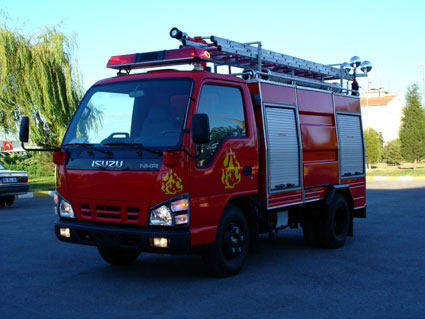
Isuzu NQR Small Fire Truck |
|
PRICE: |
Upon Request |
|
PACKING: |
Ex-works |
isuzu nqr small fire truck
|
ISUZU NQR (The Technical Specifications of Chassis)
Length, at least mm: 6610 Width, at least mm: 2015 Height, at least mm: 2200 Gross vehicle weight, kg max.: 7500 Motor: Motor volume (cc) : 4751 Model:4 HE1-T (EURO 1) Type: Turbo Diesel Max. Power (ISO GROSS) (HP/rpm) : 146/2900 Tyres: 215 /75 R-17,5 Tubeless Radial Cabin: One cab Max. speed : 100 (km/h) |
FIRE BRIGADE EQUIPMENT TECHNICAL SPECIFICATION
PRODUCT CODE: KFB3.00CR2.0NP9P
1. BODYWORK
· After the water tank is mounted on the chassis, carcass cupboards are made from profiles on the rear and on the front part of the water tank in the direction of the caldron width. After the profiles are processed they are plated with Dkp sheet iron.
· The bodywork of the equipment is manufactured as a 3 piece modular type (front cupboard-water/foam tanks-rear
cupboard) which can be dismantled whenever desired.
· The doors of the cupboards are made of aluminum material in the shape of shutters and in this way water and dust tight feature of the cupboards is realized. Opening and closing of the shutters is carried out by means of a drum.
· Catchbars and safety locks are present on the cupboard doors.
· After the bodywork is completed it is painted and the necessary parts are plated with nickel and aluminum.
· The interior parts of the cupboards are plated with diamond shaped aluminum sheets.
2. WATER TANK
· The water tank capacity is 2000±100 liters.
· The water tank can be readily dismantled off the vehicle for repair purposes if necessary.
· The water tank is manufactured of 3 mm thick AISI 304 quality chrome nickel (Ci – Ni) sheets and the whole tank is welded smoothly form the interior and the exterior by means of a gas electric welding.
· In order to prevent billowing caused by the movement of the vehicle and the water surface levels, 3 mm thick breakwaters, 1 in the transversal 1 in the longitudinal direction, are installed inside the water tank. The breakwaters are manufactured from the same material as the tank. The said covers inside the tank forms a total of 6 compartments/sections and in order to carry out the cleaning process of the tank in the compartments/sections the necessary passages are present between them.
· A manhole lid having a rubber gasket rim and that can be easily opened and closed and through which a man could easily pass is present on the tank.
· The upper surface of the tank is coated with diamond shape iron sheets having threads facing outwards in order to prevent slipping.
· A collapse reservoir having an appropriate diameter and depth is located underneath the tank and a global valve for discharging the waste water accumulated under the reservoir is present.
· To enable a person to climb on to the platform above the tank a ladder is manufactured having handles at its sides and which is placed on the rear and at the side of the tank.
· In order to discharge the compressed air and the excessive water inside the tank during the filling process of the tank, a fleeing/overflow or bluff tube is mounted which has an appropriate dimension to the pump position.
· A single filling rim, having a lid and a record, is present underneath the tank which enables filling water from an exterior form the left or the right side. A pipe, which does not contact the ceiling of the tank but rather extends up to the ceiling, is formed on the part of the filling rim which enters inside the tank and in this way during the filling process the water is filled inside the tank without being exposed to pressure.
· In order to display the water level inside the tank an electronic water level indicator is mounted on the pump control panel.
The mounting process of the tank on the chassis is made by appropriate fixing elements in order not to cause any abnormal tensions on the chassis and these fixing elements possess a feature that prevents the tank to slide back and forth and from left to right when the vehicle is full-load.
3. FOAM TANK
· Foam tank capacity is 200±50 liters.
· The foam tank is manufactured of 4 mm thick AISI 304 quality chrome nickel (Ci – Ni) sheets.
· Above the foam tank a lid with an appropriate dimension having a rubber gasket rim is present. A discharge valve is present underneath the tank for cleaning purposes.
· In order to display the foam content inside the tank an electronic foam indicator is mounted on the pump control panel.
4. FIRST INTERVENTION WHEEL
· A first aid wheel is mounted on an appropriate place of the equipment.
· The wheel is manufactured from an aluminum casting material.
· A 30 meter long hose which has 1” diameter and which is durable against grinding and breaking is wrapped around the wheel.
· A multi purpose (jet/sis) lans (water outlet adjuster) is located on the tip of the wheel.
· The wheel hoses can be winded open manually in an easy and in a rapid way and the winding back process is also carried out manually.
· In order to wind open and wind back the hose easily during the winding of the hose a bobbin system at the bottom and at the sides is present.
5. WATER AND FOAM MONITOR
· A monitor having a 1.600.-Lt/Min capacity is located on the platform which is used for spraying water/foam mixture.
· The monitor is manufactured from special aluminum alloy material and its nozzle (hood) is made from special plastic material.
· A hood which has a jetting and misting feature is located on the end of the monitor and the spraying process can be adjusted from the monitor as jet/sis.
· Controlling the monitor is performed manually and the operating levers are manufactured in an adjustable way.
· Locking elements are present in order to fix the monitor when it is not in use.
· Under a pressure of 8-10 atu the monitor can eject water at least 45 meters and foam at least 30 meters.
· Monitors all water outlets can also be used as foam outlets.
6. VALVE AND RACORDS
· All of the valves and racords to be used in the installation are stainless steel arm and global heavy service type valves.
· Racords are of the German type.
· The racords are connected to the suction and pressure hoses by means of stainless steel clamps. AV type face spanners are used for assembling and disassembling process of the records.
7- PUMP
· In order to pump the required water a light 2 level centrifuge pump which is made of special alloy aluminum and which is durable against sea water is present on the equipment.
· The pump is mounted inside the pump position made inside the equipment rear cupboard.
· The pump has at least 2000 Lt/min water flow at the 8-10 atu pressurized outlet.
· The pump has 6 outlets. Among these 4 of them (2” or 2.5”) send water to the receiving hoses, 1 of them send water to the first intervention wheel and 1 of them send water to water/foam monitor.
· The pump outlet is connected to a water tank feeding line on which there is an adjustable valve.
· On the water pump an automatic foam mixing system which is coupled to the pump by the pump factory is present.
· The pump is actuated by means of an intermediate transmission box which is manufactured specially for this purpose and which is to be mounted to the shaft that is directed to the differential.
· The pump axle is made of stainless steel and from its two ends it is embedded on the pump body by means of roller type bearings. The watertight feature of the pump is fully realized.
· In order to prevent the pump from freezing a hot water circulation system is present inside the pump.
· The pump is able to use water acquired from a water well, city main, sea water or another water source.
· One suction nozzle and a filter at the receiving section is present in the pump suction system.
· Adequate illumination system is located on the pump position which adequate to be used in night shifts.
· The pump can be controlled form the pump panel and also from the driver cabin.
· In order to adjust the pump revolution one hand throttle, low and high pressure indicators in the panel above the pump, all the necessary warning indicators, control buttons and emergency stop button is present on the control panel.
8. LADDER SYSTEM
· Two pieces 9 mt. portaible ladder on the board in the equipment.
9. ELECTRICAL SYSTEM OF THE STREET SPLINKLER EQUIPMENT
· TSEK certified electric cables are used on the equipment.
· Installation (complete electric installation) is made with quality insulation and clips by passing the cables through macarones.
· A fuse box is present for the equipment electric system.
· Above the driver seat there is an American type long swivel lamp and a speaker system in the middle section of the lamp for sirens/announcements and inside the driver cabin there is an electronic signal selector and an announcement microphone.
· Illuminating lamps are provided inside the cupboards.
· 2 projectors are provided on the equipment.
10. PAINTING THE EQUIPMENT
· The equipment is painted with 2 coats of RAL 3000 fire brigade red on top of 2 undercoat painting and the interior of the cupboards is painted with grey hammertan paint.
· On the appropriate parts of the equipment FIRE BRIGADE phrases are written backwards on the vehicle coupes with …………….. …
11. THE MATERIALS TO BE PROVIDED WITH THE EQUIPMENT
· 3 meter long 2 receiving (suction) hoses having plaited rubber string, steel wires, spiral record ends.
· 20 meter long 2 fire hoses having record ends.
· 2 hose/record/record lid key.
· 1 multi purpose (jet/sis) water lans (water outlet adjuster).
· 1 single purpose water lans.
· 1 suction filter with a valve.
· 2 Dry Chemical Powder fire extinguisher with 5 kg CO2 (minimax) capacity and 2 with 6 kg capacity.
12. TRAINING
· Adequate amount of training and maintenance training is given to the personnel of the buyer firm at our factory.
13. GUARANTEE PERIOD
· Our equipment is under guarantee for 1 year starting from the date it is delivered to the user for the defects resulting from production, assembly, material and workmanship errors.
14. OTHER
· A place for installing a spare tire is made on an appropriate place of the vehicle.
· A mudguard and dust wheels are installed on the vehicle chassis according to the design condition.
All products have EN ISO 9001:2000 quality certificates.
Specification and photos are not contractual and are subject to verification upon inspection
TAKE NOTICE!
PLEASE BE ADVISED THAT INFORMATION INCLUDED IS CONFIDENTIAL IN NATURE AND IS BASED ON PRE-EXISTING BUSINESS RELATIONSHIP WITH THE LEGAL OWNER OF PROPERTY DESCRIBED HEREIN (IF APPLICABLE). AS SUCH, UPON RECEIPT OF SAID INFORMATION THE RECEIVER ACKNOWLEDGES THAT ANY UNAUTHORIZED CONTACT WITH SAID LEGAL SELLER WILL BE CHARACTERIZED AS A BREACH OF CONFIDENTIALITY AND SAID AGREEMENT MAY BE ENFORCED UNDER EXISTING LAW OR IN EQUITY.
This paper was
prepared by General Equipment Inc.
The paper represents an offer of a partner of General Equipment Inc.
All rights are reserved by and for General Equipment Inc.
All
content and ideas of this paper are the property of General Equipment Inc.