|
|
GENERAL EQUIPMENT INC.
8724 Sunset Drive #191 ● Miami FL 33173 · USA
|
|
|
GENERAL EQUIPMENT INC.
8724 Sunset Drive #191 ● Miami FL 33173 · USA
|
336L39
|
TYPE: |
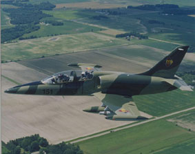
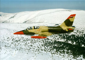
L-39 Albatros |
|
DESCRIPTION: |
As per Text Below |
|
PRICE: |
Depending on Equipment and Quantities, Upon Request |
|
PACKING: |
To be Specified |
L-39 ALBATROS
|
We offer:
1. Aircraft sourcing 2. Complete overhaul of Airframe, Systems, Avionics and Powerplant 3. Parts delivery 4. Training services
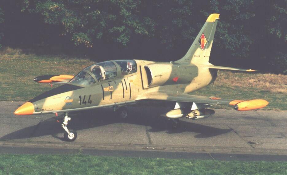
The L-39 was selected as the standard jet trainer in 1972 for the Soviet Union and the Warsaw Pact countries, with the exception of Poland and was the successor to the L-29 Delfin jet. The L-39 is a single engine, tandem two seat, all-metal, subsonic aircraft. The L-39 made its first flight on November 4, 1968. The aircraft's primary mission is basic and advanced training. The First model designated L-39C was the initial training version with two under wing stations. A total of 2,244 L-39C models had been delivered, almost all to the ex-soviet Air Force. |
The L39 is robust and has proved its qualities in the hardest climate and operational conditions. It's excellent reliability and service life ensure trouble free operation and guarantee low maintenance and operating costs. The turbofan engine offers low fuel consumption and low sensitivity to foreign object damage (FOD).
Testimony to the reliability of the L39 is proven in the number of L39 aircraft being currently used and in the repeat orders from existing customers. The Mean Time between failure in flight is higher than 300 flight hours. The probability that a one hour sortie will be successfully completed is 99.6%. The safety record of the L39, combined with its unique built in features make it the most highly cost-effective aircraft in the world for its mission.
Rapid servicing and low maintenance cost was one of the main criteria in the development of the L39. The airframe is furnished with an extensive array of access doors with quick release locks, and easily operable from the ground with simple airfield servicing equipment. The engine can be removed and fitted back in less than three hours. All parts of the airframe are replaceable and interchangeable. Overhaul of the airframe is required after 2,000 hrs and overhaul of the engine after 1,000 hrs. Proven airframe service life is 6,000 hrs.
The following versions have been produced:
L-39C ● L-39Z0 ● L-39ZA
Standard version for training and light attack, wing with two hardpoints Improved version for training, wing with four hardpoints
Ground attack and reconnaissance version with gunpod (twin barrel 23 mm) and four hardpoints under the wing.
FUSELAGE
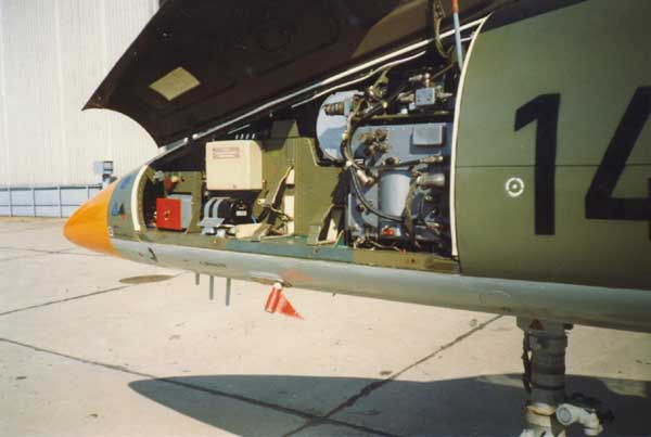
The fuselage is a metal semi-monocoque construction, built in two portions. The front portion consists of three sections, the first of which is a laminated fiberglas nose cone, housing avionics, antenna, battery, compressed air and oxygen bottles and the nose landing gear. Then comes the pressurized compartments for the crew. The third section incorporates the fuel tanks, air intakes and engine bay. The rear fuselage, carrying the tail unit, is attached by five bolts which can be removed quickly to provide access for engine installation and removal. The two air brakes are side by side under fuselage, just forward of the wing leading edge and are actuated by single hydraulic jack; these are lowered automatically as airspeed nears a maximum of mach 0,80.
WINGS
The design is a cantilever low wing monoplane, with a 2 degrees 30 minutes dihedral from wing roots. The wing section is NACA 64A012 mode 5. The wing incidence is 2 degrees, the sweepback 6 degrees 26 minutes on leading edges, 1 degree 45 minutes at quarter chord. The elevator, ailerons, and rudder are controlled through a direct mechanical system. Flaps and airbrakes are actuated by an electro hydraulic system. ln case of failure, functionality is ensured by the emergency hydraulic system. The all metal double slotted trailing edge flaps are operated by push/pull rods actuated by a single hydraulic jack.
The flaps retract automatically when airspeed reaches 167 knots (193 mph). Stall fences are installed above and below the trailing edge between flap and aileron. The ailerons are mass balanced. each with electrically operated servo tabs; the port tab is used a[so for trim and [s operated by electromechanical actuator. Flaps deflect 25 degrees for take-off, 44 degrees for landing; the ailerons deflect 16 degrees up or down; air brakes deflect 55 degrees downward. The wing tip fuel tanks are non-jettisonable and incorporate landing/taxi lights.
POWER PLANT and APU
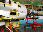
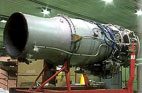
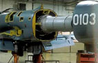
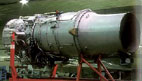
The aircraft is powered by one 3792 Ibs. AI-25 TL twin shaft turbofan engine mounted in the fuselage compartment behind the fuel tanks. The engine mounting consists of 2 + 2 suspensions located on each si de of the engine and attached to the front fuselage structure. The engine is slipped onto the fuselage in forward direction using the "U" profiles fitted on both sides of the inner fuselage space. For engine mounting and dismantling it is necessary to detach the fuselage rear part. Good access for engine and accessories servicing is ensured by doors in fuselage.
The engine is a twin spool, by-pass turbofan with a by-pass ratio of 2,0. The low pressure compressor has three stages; the high pressure compressor has nine stages. The total compressor ratio is 9,5. The combustion chamber is circular in section and has 12 single channel nozzles. The axial turbine has two shafts, three stages. The first rotates the high pressure compressor and the second and third stage rotates the low pressure compressor.
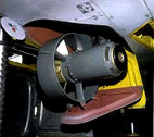
The Saphir-5 APU and SV-25 turbine are installed for engine starting. The engine is automatically started on the ground by means of an air starter that is fed by compressed air from the auxiliary power unit (APU) Saphir-5. ln the air the engine can be restarted by both APU and/or autorotation.
CONTROLS
The aircraft has conventional flight control surfaces controlled by push/pull rods operated manually by two control sticks located one in each cockpit.
The aileron and elevator have twin trim tabs actuated by coolie hat mounted on each control stick.
The movement of the rudder is controlled by two sets of adjustable pedals which are also used for differential braking.
The wing flaps are operated hydraulically and are controlled by three push buttons (0, 25, 44 degrees) located on the left hand console in both cockpits. The speed brakes are operated hydraulically and controlled by a selector located on both engine throttle levers.
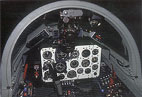
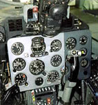
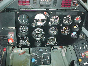
COCKPIT
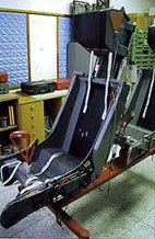
The Crew of two in tandem are installed on Czech V8-1-BRI rocket assisted ejection seats, operable at 0 height and at speeds down to 81 kts. The canopies individually hinge sideways to starboard and are jettisonable. The rear seat is slightly elevated for improved visibility. The single-piece windscreen hinges forward to provide access to front instrument panel. There is an internal transparency between front and rear cockpits.
The instrumentation of the L39 aircraft enables operation in all weather conditions by day or night. The layout is similar in both front and rear cockpits.
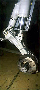
LANDING GEAR
The tricycle retractable undercarriage is designed to withstand the hardest operational conditions and is suited for concrete, grass or even unprepared runways. The main U/C wheels are equipped with hydraulically operated double-disk brakes with antiskid system. The forward retractable nose leg includes a shimmy damper. The gear is designed for touchdown sink rates of 11,5 ft/sec at auw of 10,1411 bs. Retraction/extension is operated hydraulically, with electrical actuation. All wheel doors close automatically after wheels are lowered to prevent ingress of dirt and debris. Main wheels retract inward into wings (with automatic braking during retraction). The nose wheel retracts into the forward fuselage.
SYSTEMS
Hydraulic System
The main circuit of the hydraulic system provides power for flaps, airbrakes, landing gear, ram-air-turbine, wheel brakes and the anti-skid device. Power is supplied by a variable delivery constant pressure pump working at 15 Mpa (2000 psi). The emergency circuit incorporates 3 hydraulic accumulators for ail of the above except airbrakes. Wheel brakes are operated at 500 psi.
Pneumatic System
Pneumatic canopy seals are supplied by a 2 liter compressed air bottle in the nose compartment at 2133 psi.
Electrical System
The main network is 28V DC powered by a 7,5 KVA engine driven generator. The auxiliary network is three phase of 3x115/ 200V - 400Hz. Besides the main source, the aircraft is equipped with both reserve and emergency sources. If primary generator fails a ram air turbine is extended automatically into the airstream and generates up to 3 KVA of emergency power for essential services. A 12V 28 Ah SAM 28 lead acid battery for standby power and for APU starting is installed. Two 800 VA static inverters (the first for radio equipment, ice warning lights, engine vibration measurement and air conditioning, the second for nav, landing systems, and IFF) provide 115 V single phase AC power at 400Hz. A second circuit incorporates a 500VA rotary inverter and 40VA static inverter to provide 36 V three phase AC power, also at 400Hz.
Fuel System
Fuel is contained in five rubber main tanks in the fuselage aft of the cockpit, two fixed wing-tip tanks, and two optional underwing drop tanks. Total fuel capacity is 1,995 liters. Gravity refuelling points are on top of fuselage and on each tip tank. The fuel system permits up to 20 seconds of inverted flight.
Air-conditioning and Oxygen System
The pressurized cockpit is equipped with automatic pressure and temperature regulation. Oxygen masks in both cockpits can be used for high altitude flights of a long duration. The cabin is pressurized (standard pressure differential 3,29 psi, max overpressure 4,20 psi) and air system is used and air conditioned using bleed air and a cooling unit. The air conditioning system provides automatic temperature control from 10 to 25° C to +45° C. There is a six bottle oxygen system for crew, pressure 2133 psi.
Anti-G System
Anti-G system is installed as standard and offers automatic regulation.
De-Icing System
The air intakes and windscreen are anti-iced by engine bleeding air. Anti-icing is sensor activated automatically but a standby system is also provided.
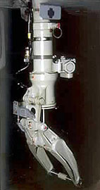
Escape system
The escape system is fully automatic and enables reliable ejection of pilots from heights 0 – 50 meters at aircraft speeds of 80 – 250 kts and from heights of 50 m up to the service ceiling at a max speed of 400 kts. Ejection is effected after canopy jettisoning. Only in an emergency when it is not possible to release the canopy is it allowed to go through the glass which is fractured by the seat headrest. The simultaneous ejection of pilots is prevented by a blocking sequencing system.
Ejection seat
The VS-1 ejection seat is a fully automatic, cartridge operated, rocket assisted seat. The parachute system consists of main parachute located in seat back pack and of stabilizer parachute placed in pilots headrest. The separation of the pilot from the seat and deployment of the main parachute is effected automatically by means of barostatic units. An integral harness system is used. A shoulder harness system allows pilot's forward movement. The correct pre-ejection posture is secured by retraction of shoulder harness by means of pyromechanism and by automatic fastening of pilot's legs. The height of the seat pan from the aircraft floor can be adjusted in a range of 180 mm. The ejection including the canopy jettisoning is controlled by double firing handles. The ejection seat is equipped with it's own oxygen system. The survival pack, with contents according to customers request, is located in the seat pan.
Lighting System
The exterior lighting system consists of nav lights, landing and taxi lights. Nav lights are located on each wing tip and on the fin. Flashing and brightness control of the nav lights is provided by means of a flasher unit. Taxi and landing Iights are installed in both wingtip tanks. The cockpits illumination is provided by lights distributed on the instrument panels and above all consoles. ln both cockpits it is possible to choose either red or white light and adjust the required brightness.
L-39C Basic data
Max speed at 16,400 ft: 407 kts - 755 km/h Max speed at Sea level: 378 kts - 700 km/h Length: 39 ft 8 in - 12,13 m Wing span: 31 ft 0 ln - 9,46 m Height: 15 ft 6in- 4,77m Wing area: 202 sq ft - 18.80m Flaps: Double slotted, fowler-type Flaps takeoff: 25 degrees Flaps landing: 44 degrees Empty weight approx: 7,625 Ibs - 3,458 kg Max ramp: 10,406 Ibs - 4,720 kg Max takeoff weight: 10,362 Ibs - 4,700 kg Max landing weight: 10,1411bs - 4,600 kg Normal takeoff weight: 9,976 Ibs - 4,525 kg Center of gravity: range 20.7 to 26% m/s Max crosswind demonstrated: 19.44 kts - 10 m/s Take off run: 1,575 ft - 485 m Landing distance: 1,968 ft - 605 m Initial rate of climb: 4,330 tt/min - 22m/s Time to 16,400 ft: 5 minutes Max vmo knots: 491 kts - 909 km/h Max load factor: +8g - 4g Max Mach n° 0,80 clean Englne Ivchenko AI-25-TL Takeoff power: 106,8% = 17,600 rpm - thrust 3,7921bs 20 mins max Climb power: 103,2% = 17,000 rpm - thrust 3,306 Ibs Unlimited Cruise power: 99,6% = 16,400 rpm - thrust 2,811 Ibs Idle run: 56% - thrust 297 Ibs, 30 minutes max on grd Range at 16,400 ft: 540 nm - 1 ,002 km
Fuel Total fuselage & tips: (332 gal. 1,014 kg, 2,241 Ibs, 1,257 lit) Max endurance: Approx. 2.5 hours on internal fuel Initial climb speed 220 knots - 407 km/h at SL Best climb at VY: 216 kias - 400 km/h to reaching a tas of 270 kts VLO: 180 knots - 333 km/h VFO: 160 knots - 296 km/h Crew: Two in tandem Ejection seats: VS-1-BRI
Specification and photos are not contractual and are subject to verification upon inspection
NB: Aircraft offered for sale subject to contract, prior sale, withdrawal from the market and information regarding any aircraft or helicopter and provided verbally or in written documentation and/or contained within this offer or associated paper-work should be taken as a guide only in determining the suitability, including that aircraft or helicopters specification and/or performance. We highly recommend that any buyer or lessee perform their own inspections and due diligence to verify any and all technical, performance and specification information contained therein including OEM claims.
TAKE NOTICE!
PLEASE BE ADVISED THAT INFORMATION INCLUDED IS CONFIDENTIAL IN NATURE AND IS BASED ON PREXISTING BUSINESS RELATIONSHIP WITH THE LEGAL OWNER OF PROPERTY DESCRIBED HEREIN (IF APPLICABLE). AS SUCH, UPON RECEIPT OF SAID INFORMATION THE RECEIVER AKNOWLEDGES THAT ANY UNAUTHORIZED CONTACT WITH SAID LEGAL OWNER WILL BE CHARACTERIZED AS A BREACH OF CONFIDENTIALITY AND SAID AGREEMENT MAY BE ENFORCED UNDER EXISTING LAW OR IN EQUITY.
This paper was prepared by
General Equipment Corp.
The paper represents an offer of a partner of General Equipment Corp.
All rights are reserved by and for General Equipment Corp..
All
content and ideas of this paper are the property of General Equipment Corp.
Defense items are subject to final destination approval and granting of an
export license issued by exporting country's authorities