|
|
GENERAL EQUIPMENT INC.
8724 Sunset Drive #191● Miami FL 33173 · USA
|
|
|
GENERAL EQUIPMENT INC.
8724 Sunset Drive #191● Miami FL 33173 · USA
|
30 MW
| TYPE: | Power Plant |
| DESCRIPTION: | 30 MW Power Plant 50Hz |
| PRICE: | Upon Request |
| PACKING: | Ex-Depot |
30 MW POWER PLANT
Combined Cycle Power Plant
Output: Power 30 MW, 50 Hz
Heat 30 MW

1. General
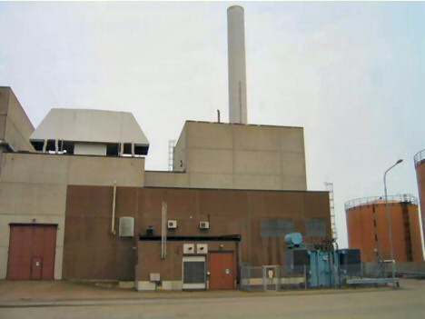
The offered CCPP (Combined Cycle Power Plant) is located in Sweden, Europe and is due to changed operation request today in standby mode, can be started on request at load condition. The plant was operated for Power Generation and District Heat for the nearby city. Due to the new changed boundary condition with wood chips as main fuel supply for the district heating the owner decided to de- invest this relatively new unit in excellent condition. The entire Electro- Mechanical Equipment is therefore for sale and offer for relocation.
The plant is:
- In excellent condition
- Well maintained
- Relatively new
- Available now
- Service and support for future operation
2. Plant Description
The Combined Cycle Power Plant is operated in CO-generation mode. It is presently installed in a district power/heat plant and has been commercially operated from 1992 until today.
The plant consists of main components:
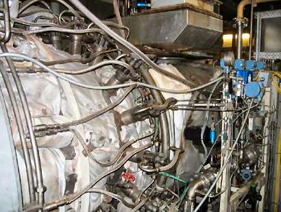
- Gas Turbine, ABB GT 10 with capacity of 23,250 MW.
- A high pressure Heat Recovery Steam Boiler with additional direct firing facility (natural gas) of 30 MW for district heating and steam for Steam Turbine.
- An existing counter-pressure Steam Turbine ABB Stal, with a capacity of 7.2 MW.
- All associated Auxiliaries for the mechanical and electrical CCPP operation mode
3. Plant Operation
With the gas turbine on full load the heat recovery boiler will produce 30 MW for district heating and steam to the ST for 7.2 MW electricity. If the Gas Turbine is not in operation the additional direct firing facility in the boiler will produce 30 MW district heating. The steam turbine can be operated under this condition as well.
The plant which has been regularly serviced and maintained by the OEM is fully automated and is controlled by a qualified Engineer. Starting of the plant is done in the control area or from the central control room.
4. Performance Data
The designed basic output of the Plant is:
- 30 MW electric Power
- 30 MW Heat output
With a fuel input of approx. 70 MW
At ISO Condition and Co- Generation operation the plant is designed at ISO Condition
Electrical efficiency > 42 %
Fuel usage factor > 86 %
Details of performance are depend of local boundary and ambient conditions (e.g.
district heating temperature, site level, etc.) of new site and have to be defined with new
operator and adjusted to new site condition.
5. Scope and Delivery
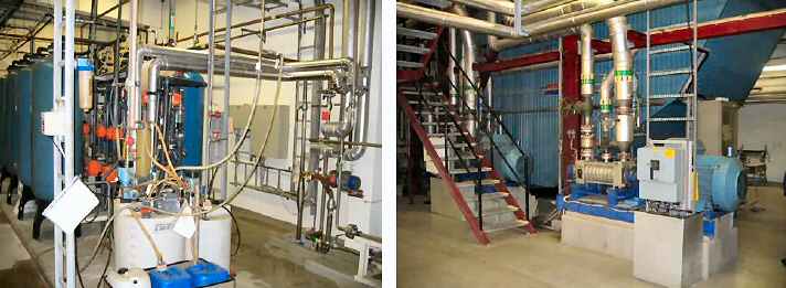
5.1 Equipment
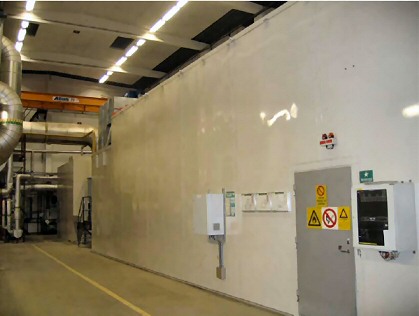
Basically the entire existing mechanical and electrical Equipment of the combined cycle process is part of the delivery scope including the Demi- Water plant. Building structure, building itself and building facilities (lightning, small power supply, etc.) is not part of the delivery scope.
Main component:
- Turbo Group with Gas Turbine, Generator, Steam Turbine and main Gears
- A high pressure Steam Boiler for Heat Recovery and with direct firing facility (natural gas) of 30 MW for district heating and steam to Steam Turbine.
- All associated mechanical Auxiliaries, e.g. pumps, drums, vales, air filter, stake, etc.
- Control instrumentation system including local control station; central control room is part of the district heating plant and therefore excluded from the delivery scope
- Fire- alarm and fighting system, Gas detection system
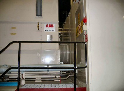
- All associated electrical Auxiliaries, e.g. motors, motor switch board, batteries, etc.
- Demi- Water plant with a capacity of 7 m3/h
- Technical documentation as it is available with the operator
Connection elements like piping, electrical cables depend on customer’s request.
5.2 Services
The scope of equipment will be by the seller and the current operator demounted, cleaned and seaworthy packed. The demounting work of the turbo group will be supervised by a specialist from the OEM. Interfaces of components will be marked to allow a professional reassembly. It is recommended that a supervisor of the reassembling company participate the entire process of dismantling at customers costs in order to facilitate the re assembly process.
The full set of technical documentation will delivered in the condition as it is available in hard and soft copies in English and partly in Swedish language. Number of sets as it is currently available at operator site and offices.
Packed components will be delivered at the deep water seaport Helsingborg Sweden at FAC condition (Free alongside Carrier).
6. Option
For the current local city power-supply security this plant has been originally equipped with a Diesel Generator group as black-start facilities. In general, such a Black Start facility is in most Power Plant application not needed is not usual Plant equipment. The Diesel Generator group has approx. 120 operating only. In the Turbo- group hall a heavy lift overhead crane is permanently installed. The buildings, including the building facilities will be reused for the installation of new biomass boilers with its auxiliaries. For this new installation the overhead crane is in principle foreseen as building facility. Discussion with current operator is ongoing if this overhead crane can be dismantled and relocated as well.
If the new operator is interested in the useful incremental facilities, Diesel Generator and Crane can be acquired at favourable conditions.
7. Commercial Condition
7.1 Delivery condition:
The equipment is offered on the condition
- dismantled, cleaned and packed
- FAC seaport Sweden
Crane on request
Payment condition
After a principal agreement and payment of advanced payment fee Seller will initiate a draft for a sales and purchase agreement between the parties. It is not yet fully decided if there will be one or two individual agreement and the legal contract partners; a decision will be based on a mutual understanding between the parties.
Commercial Conditions of this offer:
All equipment is quoted “where it is and as is”, subject to inspection and prior sale unless otherwise indicated. Scope-of-supply must be verified by customer during inspection. Seller is not responsible for errors or omissions during site visit. The terms of this proposal are non-binding and the recipient of this proposal (and their respective subsidiaries and affiliates) will be subject to the execution of a final contract acceptable to both parties.
Taxes, Licenses and Fees:
Buyer should be responsible for all equipment duties, taxes of all kind and license fees imposed by the national and-local government.
Disclaimer of other Warranties
Unless other agreement it is expressly understood and agreed that seller makes no warranty and assumes no responsibility, expressed or implied, for the condition, performance, maintenance, manufacture, or design of the goods. Seller makes no other representation and disclaims any other warranty, whether statuary, written, oral, express, or implied, including but not limited to any warranties of merchantability, fitness for a particular purpose or arising out of any course of dealing or usage of trade.
Any information provided by seller which relates to the goods is or will be for information only and is not and will not be guaranteed or warranted.
Specification and photos are not contractual and are subject to verification upon inspection
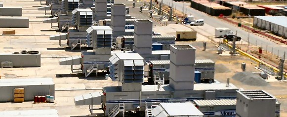
TM2500 Turbines
8 X TM2500 Turbines for Sale
Please find attached all the information & pricing for the TM2500 Turbines so if you would like to move forward feel free to contact us anytime.
These are duel frequency 50/60 HZ
See details at:

31 mw Mobilpac


|
Delivery
2 in 30 days - 2 in 60 day
Gross HEAT RATE @ ISO 9312 BTU/KWE
Lube oil system. Combined gas generator & power turbine
Fuel supply system ( Dual Fuel )
Buffered air system
Water injection NOx control system, mounted in lube oil system enclosure
Two-stage Inlet air filter for COASTAL ENVIRONMENT with weather hood. 1 stage pre-filter. 2 stage high efficiency media.
Inlet and exhaust silencing. Two inlet sections
Exhaust interface . EXHAUST STACK.
- Stainless steel piping downstream of filter
Enclosure. Prime painted
Operation Control Cabinet
Monitoring cabinet
Instrument cabinet
Unit control cabinet (Engine A)
Unit control cabinet (Engine B)
Generator protective relay panel
Motor Control Center
Master Terminal Cabinet
Ventilated cubicle with rack mounted lead acid batteries (24 VDC and 126 VDC) Battery chargers Switch gear module 15 KV Class
Interconnecting piping for lube oil, hydraulic start and water injection (between PWPS supplied skids and CTG only).
Foundation embedded material (Includes anchor bolts, shims and plates)
Interconnecting electrical cables (Between PWPS supplied skids and CTG)
N/A
|
See details at:
Mitsubishi FT8 MOBILEPAC Gas Turbine Package.pdf
TAKE NOTICE!
PLEASE BE ADVISED THAT INFORMATION INCLUDED IS CONFIDENTIAL IN NATURE AND IS BASED ON PRE-EXISTING BUSINESS RELATIONSHIP WITH THE LEGAL OWNER OF PROPERTY DESCRIBED HEREIN (IF APPLICABLE). AS SUCH, UPON RECEIPT OF SAID INFORMATION THE RECEIVER ACKNOWLEDGES THAT ANY UNAUTHORIZED CONTACT WITH SAID LEGAL SELLER WILL BE CHARACTERIZED AS A BREACH OF CONFIDENTIALITY AND SAID AGREEMENT MAY BE ENFORCED UNDER EXISTING LAW OR IN EQUITY.
This paper was prepared by General Equipment Inc.
The paper represents an offer of a partner of General Equipment Inc.
All rights are reserved by and for General Equipment Inc.
All content and ideas of this paper are the property of General Equipment Inc.